THRUSH AIRCRAFT, INC – MODEL S2R-R1340
AIRCRAFT MAINTENANCE MANUAL
8-6
Effective: 01/01/08
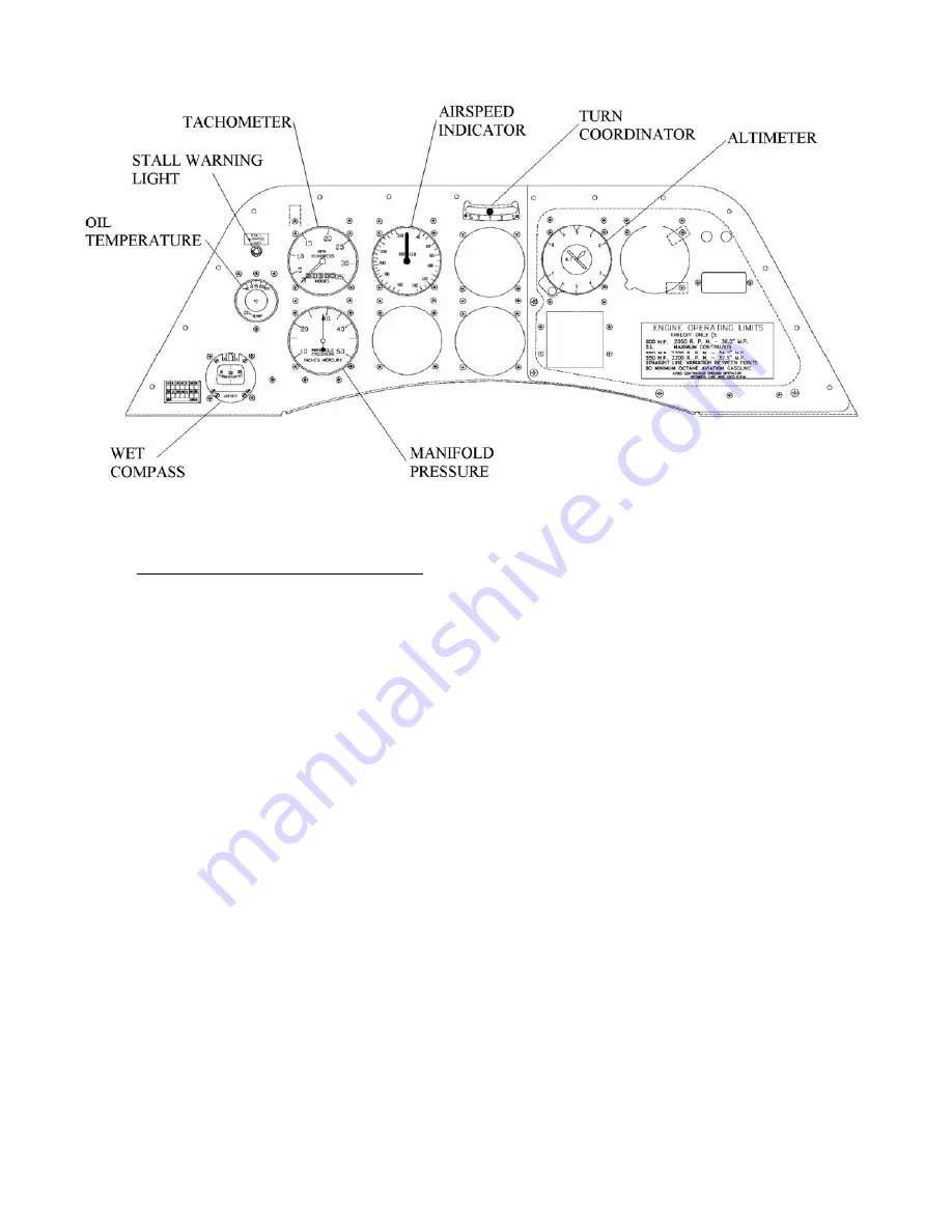
Figure 8-2: Center Instrument Panel
Magnetic Compass Compensation
Locate the aircraft in area suitable for
the method of magnetic compass
compensation to be used. Close doors
and place flaps in a retracted position.
Set the throttle at cruise position with
engine operating. Place all electrical
switches, alternator, radio and other
equipment in a mode normally used in
flight and proceed with the following:
A.
Set adjustment screws of
compensating magnets to zero.
Zero position is when the dot on the
screw is lined up with the dot on the
compass frame.
B. Position aircraft in a magnetically
north direction. Use an approved
Compass Rose if at all possible.
Adjust north-south adjustment screw
until compass reads exactly north.
C. Position aircraft in a magnetically
east direction. Adjust east-west
adjustment screw until compass
reads exactly east.
D. Position aircraft in a magnetically
south direction. Notice the resulting
south error. Adjust north-south
adjustment screw so that one-half of
the error has been removed.
E. Position aircraft in a magnetically
west direction. Notice the resulting
west error. Adjust east-west
adjustment screw so that one-half of
the error has been removed.
F. Recheck the magnetically north and
east directions to confirm that the
error is the same as for south and
west.
G. Position aircraft in successive
magnetically 30-degree directions
and record all errors on the deviation
card furnished with the compass.
TURN COORDINATOR
The turn coordinator, installed in the
center of the upper instrument panel, is
a curved, fluid-filled tube containing a
ball. The gravitational and centrifugal
forces position the ball within the tube to
indicate a coordinated turn. A correctly
coordinated turn is indicated by a
centered ball, no matter what the bank
angle. An off center ball indicates that
additional rudder is needed on the side
the ball is off to.


