background image

-18-

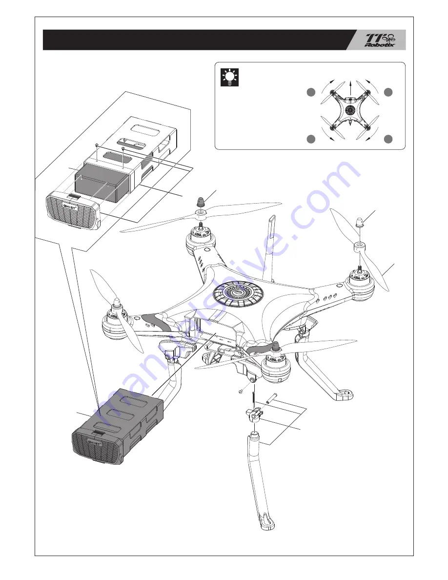
EXPLODED VIEW

2850

PV1805

PV1811

AC7180

AC7180

PV1803

2852

Diagram for Propeller 
Assembly

Please note the orientation 
of the propeller. If they are 
not assembled properly as 
illustrated, quadcopter can 
not takeoff and result in 
unexpected damage

C.W.

C.W.

C.C.W

FRONT

C.C.W.

M3

M4

M1

M2

Summary of Contents for Ghost plus

Page 1: ...he market 5 Built in Follow Me function let your quadcopter can Follow You to everywhere 6 Retractable landing skids provide better view of the camera lens 7 High performance 3 Axis gimbal suitable for the GOPRO Optional 8 High performance handycam carrier for the Sony PJ series Optional SPECIFICATIONS Product Name Frame type Diagonal distance Frame weight Motor stator size Motor KV ESC current ES...

Page 2: ... date of purchase Removal or tampering of the WARRANTY VOID stickers from the Product voids this warranty This warranty is not transferable and does not cover cosmetic damage or damage due to acts of God accident misuse abuse negligence commercial use or due to improper use installation operation maintenance or modification of or to any part of the Product or attempted service by anyone other than...

Page 3: ...r Scissors OPTIONAL PARTS ACCESSORY Handycam Gimbal SONY PJ Series FPV Set 5 8G 11 Propeller Set 4pcs Smart Phone Holder Set 6S Li Po Battery Balance Charger for Li Po Battery Hex Wrench Set 2 5mm 2mm 1 5mm Landing Skid Set 4pcs Compass Holder Wrench 2 4G Radio GHOST GOPRO 3 Axis Gimbal OSD Unit ...

Page 4: ...act Landing Skid Direction Lights FRONT VIEW Battery Capacity Indicators Power Switch Battery Box TOP VIEW BOTTOM VIEW Binding Button Flight Status Indicators Micro USB Port 24V Power Wire Out Gimbal Signal Wire Out Y1 Gimbal Signal Wire Out Y2 ...

Page 5: ...tick Stick Mode Switch Charger Jack Intelligent Mode Switch Gimbal Angle Knob Roll Pan Binding Button Power Switch Mode 1 Mode 2 Quadcopter Movement Aileron Elevator Rudder Throttle BASIC FLIGHT OPERATION Forward Direction Indicates Front Side Front Front Front Front Up Down Backward Forward Right Left Right Left ...

Page 6: ...aw Control 4 CH 5 Intelligent Mode IOC Intelligent Orientation Control IOC OFF When IOC switches to the OFF mode the IOC function will be dismissed IOC ON When IOC switches to the ON mode the quadcopter will be heading locked intelligently and oriented to its original take off point 5 CH 6 Flight Mode Take Off Mode When the GPS antenna receives 7 signals from the satellite it will switch to the GP...

Page 7: ...ntelligent Orientation Control IOC OFF When IOC switches to the OFF mode the IOC function will be dismissed IOC ON When IOC switches to the ON mode the quadcopter will be heading locked intelligently and oriented to its original take off point 5 CH 6 Flight Mode Take Off Mode When the GPS antenna receives 7 signals from the satellite it will switch to the GPS mode automatically Landing Assist The ...

Page 8: ...s advised that you watch the tutorial videos and this manual completely before flying the quadcopter CAUTION More information can view the tutorial videos on our TTR official website www ttrobotix com or YouTube channel https www youtube com user ThunderTigerVideo QUICK START GUIDE Install left and right side the same way 1 Make sure skid assembled as shown 2 Make sure hex bolt head fit into the h...

Page 9: ... 08 Put the compass set into the body as shown and secure screws tightly COMPASS SET DO NOT pull the connected wire too hard Phillips Tapping Screw M2 5 x 8 ...

Page 10: ...mage Install the propeller on the motor shaft and use the adapter to tighten the propellers Be sure to match the rotate direction sign on propeller and body arm Install left and right side the same way Ensure props rotate freely after assembly Do not use threadlocker and do not over tighten adapter Silver adapter for clockwise motor shaft M1 M3 FRONT C C W M3 C W M4 C C W M1 C W M2 Make sure the d...

Page 11: ... 10 SMART PHONE HOLDER Assembly the smart phone holder as shown and use the socket screws to correctly attach the smart phone holder on the radio ...

Page 12: ...please change battery CAUTION BATTERY BOX 6S battery power wire 1 pcs of 6S battery link introduction 6S battery balance charger connector 2 pcs of 3S batteries link introduction 3S battery 2 balance charger connector Main power connector link to charger or body Main power connector link to charger or body 3S battery 1 balance charger connector 3S Battery 1 XT60 connector 3S Battery 2 XT60 connect...

Page 13: ...t landing position during landing but CAN NOT push the throttle stick 100 90 10 80 70 60 50 40 30 20 You can see the current battery capacity from the indicator Refer to the following photo for details The indicators are defined below LED is GREEN LED is RED LED is YELLOW Description Flight Status LED situation Horizontal Alignment Vertical Alignment Manual altitude Satellite 4 Manual altitude Sat...

Page 14: ...he TTR HERO App TTR HERO APP CONNECTION 1 Make sure the Wi Fi function on your smart phone is switched on 2 Connect to the SSID TTRXXXXXXX and enter the password from the factory which should appear in your Wi Fi signals list approx 3 Click the TTR HERO App on your smart phone TTRXXXXXXX DOWNLOAD APP FOR FREE NOW TTR HERO Scan QR Code above ...

Page 15: ...en successful If not then need to do the calibration again OK NG 3 Carefully rotate Ghost horizontally two times Ensure that the Green LED light remains ON during this procedure 4 Click Magnetic Compass button again then select Vertical Alignment and click OK button to start Vertical calibration 5 Carefully rotate Ghost horizontally two times Ensure that the Red LED light remains ON during this pr...

Page 16: ...then turn on the Ghost power 3 If you want to use your smart phone please make sure TTR HERO App is well connected and switched on 4 Pull both sticks on the radio as shown to start motors and start flying 5 Pull the throttle stick to bottom as shown to stop motors after landing Stop the motors after the Ghost landed DO NOT stop the motors during flight CAUTION ...

Page 17: ... 8047 G Front PV1814 PV1813 AQ6551 PV1814 PV1808 PV1813 PV1813 2390L AQ6470 Use the RED direction light module Use the GREEN direction light module Secure all screws shown on this page the marked parts with dropping a few threadlocker especially The Front Arrow MUST point towards the front side of the quadcopter ...

Page 18: ... 17 EXPLODED VIEW Secure all screws shown on this page the marked parts with dropping a few threadlocker especially PV1812 PV1813 PV1813 PV1813 PV1813 PV1809 PV1813 PV1813 PV1807 PV1806 AQ6546 PV1813 ...

Page 19: ...0 AC7180 PV1803 2852 Diagram for Propeller Assembly Please note the orientation of the propeller If they are not assembled properly as illustrated quadcopter can not takeoff and result in unexpected damage C W C W C C W FRONT C C W M3 M4 M1 M2 ...

Page 20: ...V AT6203 POWER CONNECTING WIRE AQ6545 GPS MODULE PV1811 PROPELLER SET 1150 2PCS PV1807 RETRACT SKID GEAR BOX B SET AQ6468 MAIN POWER SYSTEM BOARD PV1812 BATTERY TRAY 2390R BL MOTOR C W OBL M2814 450KV PV1803 BATTERY BOX AQ6546 COMPASS MODULE PV1804 POWER LIGHT COVER AQ6469 POWER DISPLAY LED MODULE PV1813 SCREW SET AC7180 PROPELLER ADAPTER SET 2PCS AQ6550 WIFI MODULE SET GHOST PV1808 LED CASE x8 x8...

Page 21: ... 8034 FPV SET 5 8G AP0002 HANDYCAM GIMBAL SONY PJ SERIES 8035 OSD UNIT 2850 BATTERY 6S 6000mAh 2852 BATTERY SET W BATTERY BOX 6S 6000mAh 8036 HERO FLIGHT CONTROL SYSTEM GHOST 8047 G ESC 30A OPTO 8901 2 4G RADIO SET AP0003 3 AXIS GIMBAL GOPRO ...

Page 22: ...buted by Vertrieb THUNDER TIGER EUROPE GmbH Rudolf Diesel Str 1 86453 Dasing Germany For customer service please contact service thundertiger europe com North America Germany Netherlands Belgium Luxembourg Austria Italy Distributed by Vertrieb Thunder Tiger Corporation No 7 6th Road Industry Park Taichung Taiwan 40755 For customer service please contact service thundertiger com For Other Countries...

Reviews: