-17-
TAIL UNIT-TORQUE-TUBE /
尾部總成組裝-軸傳版
Bag N
HNX2-10B
SOCKET BUTTON HEAD SELF TAPPING SCREW, M2×10
半圓頭內六角自攻螺絲 M2×10
HSA2-6
BUTTON HEAD SOCKET SCREW, M2X6
半圓頭內六角螺絲
M2X6
Ensure the leading edge of the blades rotate this way as drawing.
(Turn the Main Gear clockwise, both the main rotor head and tail rotor head turn clockwise)
請注意旋翼轉動方向應與圖示相同。
(順時針方向撥動主齒盤時,主旋翼頭及尾旋翼皆朝順時針轉動。)
(12)
(4)
(3)
(1)
(1)
(2)
(2)
(12)
Step 1 /
步驟一
Insert the Bracket Spacers into the Tail Boom Bracket, and then secure into the main frames.
將固定座支柱穿入尾管固定座中後,鎖固於側板上。
Step 2 /
步驟二
1. Insert the tail boom through the bracket and push to the end.
Check the mess of the front bevel gear set by rotating the
main gear set, both main & tail rotor head rotates effortlessly
if the mess is proper. Please pull the tail boom a little bit
backward if the rotation is not smooth.
2. Tighten the 4 lower Tapping Screws to fix the tail boom on
the bracket.
TORQUE-TUBE
T22
1. 將尾管插入固定座中並推至底。撥動主齒盤組確認前傘齒
組齒隙,如齒隙正確則主旋翼及尾旋翼均會順暢轉動。如
轉動不順暢,請將尾管稍向後拉,以獲得正確齒隙。
2. 鎖緊下方兩側4顆螺絲,將尾管迫緊於固定座上。
HMJ12-6B
TAPPING SCREW M1.2×6
圓頭十字自攻螺絲
M1.2×6
HNN2-10B
TAPPING SCREW(W/WASHER) M2×10
圓頭墊圈自攻螺絲
M2×10
No.
1
2
3
4
5
6
Qty
2
2
2
2
8
1
Material No.
BK1082
HMJ12-6B
BK0923
HNN2-10B
HNX2-10B
HMV1060ZZY
Description
ROD GUIDE
TAPPING SCREW M1.2×6
TAIL SERVO TRAY
TAPPING SCREW(W/WASHER) M2×10
SOCKET BUTTON HGAD SELF TAPPING SCREW, M2x6
BERING, d6xD10xW3
名稱
固定環
圓頭十字自攻螺絲
M1.2×6
尾伺服機座
圓頭墊圈自攻螺絲
M2×10
半圓內六角頭自攻螺絲, M2x6
滾珠軸承, d6xD10xW3
No.
7
8
9
10
11
12
Qty
1
1
1
2
1
4
Material No.
BK1897-1
HMV1370ZZY
BK1567
BK1886
BK2610
HSA2-6
Description
FRONT BEVEL GEAR MOUNT
BEARING d7XD13xW4
FRONT BEVEL GEAR 11T
BRACKET SPACER
TAIL BOOM BRACKET
BUTTON HEAD SOCKET SCREW, M2x6
名稱
前傘齒輪座
珠軸承, d7xD13xW4
傘齒輪 11T
固定座支柱
尾管固定座
半圓頭內六角螺絲
M2x6
(9)
(8)
(11)
(10)
(6)
(5)
(5)
(7)
Ensure smooth, non-binding movement when assembling
確認組件靈活度
Apply threadlocker
使用螺絲防鬆膠
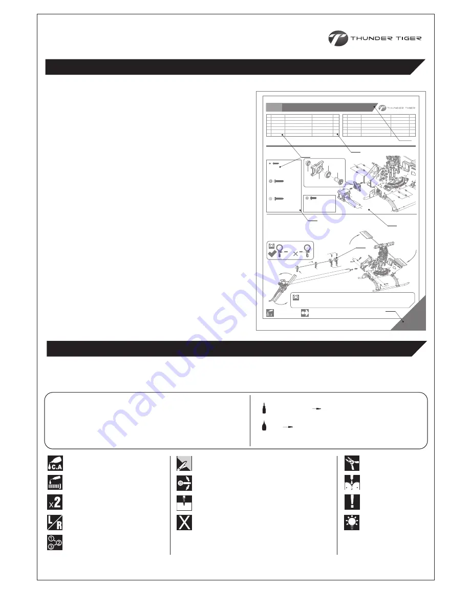
How to read the instruction manual?
說明書導讀
A:
Indicates the assembly step number and the parts bags
that are to be assembled.
B:
Displays actual size drawings, and part quantities used.
C:
All parts, except screws, are identified by its order
numbers. When purchasing spare parts, identify the part
required and cross reference this to the spare parts list in
the end of this maunal, which shows the purchasable
spare parts and the corresponding order numbers.
D:
This instruction manual uses several symbols. Pay careful
attention to them during construction. Details are given
at the bottom of each page.
E:
If a label marked here indicates the page is the exclusive
assembly steps for a particular model type; please follow
the exclusive instructions according to the model type you
purchased.
A:
顯示組立步驟及需組立之零件包順序。
B:
零件實際對照尺寸及使用數量。
C:
請比對零件形狀以及後附零件料號對照圖示找出需求零件料號。
D:
操作說明符號可更有效協助組裝者使用此說明書,請依說明書符
號指示進行組裝步驟。
E:
出現此標籤表示本頁為特定模型版本之專屬組裝說明,請依您所
購買之版本依說明進行組裝步驟。
Example
說明範例
C
B
A
B
E
D
C
T22(#262)
THREADLOCKER /
螺絲防鬆膠
CA CA GLUE /
快乾膠
Note /
注意
Assembly drawings will contain icons that indicate use of
Threadlocker or CA glue as needed.
Examples of the icons are as right shown:
請依組裝步驟圖示,使用防鬆膠或接著劑。
圖示範例如右:
-5-
Apply CA Glue
使用快乾膠黏合
Assemble as many times as specified
依指示組裝所需數量
Assemble left and right side the same way
左右側組件相同
Assemble in right order
依標示順序組裝
Drill holes with the specified diameter
依標示尺寸鑽孔
Hint
組裝提示
Must be purchased separately
改裝品需另購
Cut off shaded portion
依標示部分裁切
Ensure smooth, non-binding movement when assembling
確認組件靈活度
Pay close attention here
注意組裝步驟
Cut off excess
裁剪多餘部分
Apply grease
使用潤滑油膏(黃油)
Apply threadlocker
使用螺絲防鬆膠
The parts in the kit are packed according to each major assembly steps. The part number and quantity are always shown
in the square box on each page. As good practice, only open up the bag that you need for the paticular assembly.
零件均依照組裝步驟包裝,請依照組裝程序,逐一開啟零件包,避免零件遺失。
Note /
注意
MANUAL FORMAT /
說明書使用方式
SYMBOLS USED THROUGHOUT THE MANUAL /
符號說明


