background image

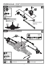
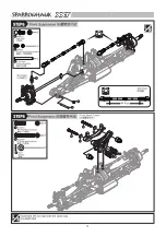
STEP6

4

2

4

4

4

3

2

1

1

4

3

2

4

1

3

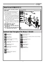
Manual Format

oil

C.A

1

2

3

說明書使用方式

A

B

C

C

D

2

How to read the instruction manual?

Must be purchased separately

改裝品需另購

 Apply C.A Glue

使用快乾膠黏合

 Apply silicon oil

使用模型專用矽油

 Assemble as many  times  as specified

依指示組裝所需數量

 Assemble left and right side the same way

左右側組件相同

 Assemble in right order

依標示順序組裝

 Drill holes with the specified diameter

依標示尺寸鑽孔

 Cut off shaded portion

依標示部分裁切

Ensure smooth, non-binding movement when assembling

確認組件靈活度

Pay close attention here

注意組裝步驟

Cut off excess

裁剪多餘部分

Apply threadlocker

使用螺絲防鬆膠

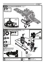
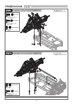
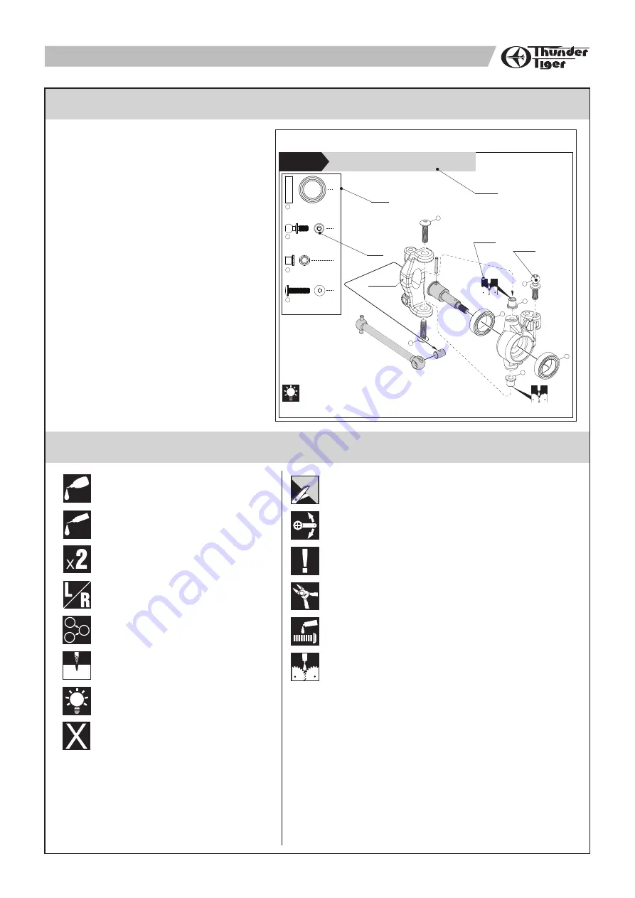
Front Suspension 

前擺臂懸吊組

6mm

Ball Stud

球頭座

10x15x4mm

Ball Bearing

軸承

3x12mm

BT Machine Screw

圓頭十字螺絲

Caster Block Bushing

C

型輪座 

In the chassis set, these dog bones have been assembled in one-piece unit.


原廠已組配完成

Marked "L"

標示 

"L"

Apply grease

使用潤滑油膏(黃油)

Example 

說明範例

Symbols Used Throughout The Manual

 Hint

組裝提示

A:

B:

C:

D:

A:
B:
C:

D:

符號說明

說明書導讀

The manual indicates the assembly step number 
and the parts that are to be assembled.
The manual displays actual size drawings, and 
part quantities used.
All parts, except screws, are identified by their 
order numbers.  When purchasing spare parts, 
identify the part required and cross reference 
this  to  the  spare  parts  list  in  the  end  of  this 
manual, which shows the spare parts and the 
corresponding order numbers.
This instruction manual uses several symbols. 
Pay  careful  attention  to  them  during 
construction.  Details are given at the bottom of 
each page.

顯示組立步驟及需組立之零件部位
零件實際對照尺寸及使用數量
請比對零件形狀以及後附零件料號對照圖示找
出需求零件料號
操作說明符號可更有效協助組裝者使用此說明
書,請依說明書符號指示進行組裝步驟

Summary of Contents for Sparrowhawk XXT

Page 1: ...this manual completely before attempting to start maintenance Follow the directions in this manual closely to reduce problems during operation We offer online help on our www acehobby com or www thund...

Page 2: ...into plastic parts A power screwdriver s high rotation speed can heat up the screw being installed which can result in some melting of the plastic parts or stripped threads 4 For best performance it...

Page 3: ...ster Block Bushing C In the chassis set these dog bones have been assembled in one piece unit Marked L L Apply grease Example Symbols Used Throughout The Manual Hint A B C D A B C D The manual indicat...

Page 4: ...3x5mm Washer 3 5x8mm Washer 4 4 4x0 9mm O Ring O 5 3x19mm Pin 6 5 4 3 6 3 1 1 2 1 1 5 4 4 5 5 X2 X2 7 m m Side View Apply threadlocker Standard Optional 2 1 3 3 1 3x3mm Set Screw 1 1 2 5 mm E clip E 2...

Page 5: ...ee P 5 5 Camber Adjustment For Ready Set Camber Linkage For Optional Turnbuckle Linkage Not Recommended Set Up 6mm S Ball Stud 3x10mm F H Philip Machine Screw Inner Hinge Pin By replacing the suspensi...

Page 6: ......

Page 7: ...her 1 2 4 3x25 mm BT Philip Machine Screw 2 2 3x16 mm BT Philip Machine Screw 3 Rear Suspension STEP4 Front Differential Unit STEP5 2 5x11x4 mm Ball Bearing 1 2 5mm E clip E 2 1 1 4x3mm Set Screw 3 Hi...

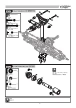
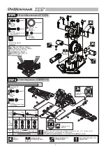
Page 8: ...P5 Front Suspension STEP6 2 3 2 1 1 Pay close attention here Apply threadlocker Hint Always adjust the front and rear bushings at the same time Your car may not run stable if front and rear bushings a...

Page 9: ...T Machine Screw 4 4 10x15x4 mm Ball Bearing 1 6mm L Ball Stud 2 2 Caster Block Bushing C 3 2 4 1 3 3 1 Marked L L Marked R R A B A B A A Toe Adjustment For Ready Set Steering Linkage For Optional Turn...

Page 10: ...52 8...

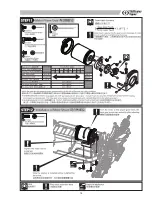
Page 11: ...x2 2 X4 Ensure the piston moves smoothly Then gently move the shaft piston up and down to get rid of the bubbles Add silicon oil one more time up to the brim Put the shock bladder onto the shock body...

Page 12: ...4 Front Shock Absorbers Rear Shock Absorbers Shock Absorber STEP7 M3 Lock Nut 3mm Washer 4 2 1 1 2 2 1 2 1 1 2 11...

Page 13: ......

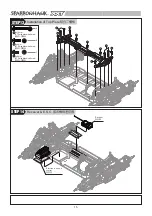
Page 14: ...EP9 1 3 3x10mm F H Philip Machine Screw 2 3x8mm BT Philip Machine Screw 1 3 M3 Lock Nut 2 Rear Suspensison 3 1 3 2 1 1 Installation of Front End 1 1 2 3 M3 Lock Nut 3x10mm F H Philip Machine Screw 1 2...

Page 15: ......

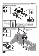
Page 16: ...x18mm BT Philip Machine Screw 2 3x8mm BT Philip Machine Screw 6 1 3x6mm BT Philip Machine Screw STEP13 Installation of Top Plate 1 STEP14 Receiver E S C 3 Receiver Electronic speed control 1 2 2 1 2 2...

Page 17: ...our servo from the chart Install the servo horn arm with the stock mounting screw See the graphic for the correct neutral angle T 90 Steering Servo Type Servo Hom Mount ACE R C S1903 S2008MG ACE R C D...

Page 18: ...nd the tire on both sides Warning Follow the adhesive instructions for proper use and safety Wear eye and hand protection 1 3x12mm Socket Hex Machine Screw STEP16 Installation of battery pack Assemble...

Page 19: ...and right side the same way 18 STEP17 STEP18 Tire Wheels Body Shell 1 M4 LOCK NUT FLANGE 2 2x10mm Pin 4 4 4 4 4 1 1 1 3 2 2 2 2 1 1 3x8mm BT Self Tapping Screw w washer Receiver Antenna Hole 2 3 3 3x2...

Page 20: ...D7905 PD9055 1 PD9055 1 PD9055 1 PD9055 1 PD7441 PD9051 PD9124 PD9124 PD7905 PD7441 PD9219 PD9213 PD9223 PD9210 PD9224 PD9210 PD9222 PD9222 PD9215 PD9223 PD7902 PD1598 PD9055 1 PD1598 PD9201 PD9055 1...

Page 21: ...D9129 PD9203 PD9203 PD7984 PD6606 PD1562 PD7736 PD7736 PD7735 PD7735 PD7736 PD7736 PD7915 PD7931 PD7944 PD9217 PD9133 PD9133 PD9217 PD7994 PD7994 PD9078 PD9078 PD9104 PD9104 PD9104 PD9268 PD7931 PD660...

Page 22: ...PD9104 PD9129 PD9090 PD9129 PD9205 PD9205 PD9129 PD9090 PD7984 PD6606 PD6606 PD7984 PD9203 PD9203 PD9203 PD9203 PD1562 PD1562 PD7994 PD7978 PD9133 PD7736 PD7736 PD7978 PD7994 PD9133 PD9217 PD7916 PD11...

Page 23: ...92 E D C PD9207 PD7922 PD7846 PD7942 PD7712 E PD1713 PD9211 PD7314 PD1713 PD1532 PD2488 PD9211 C PD1532 PD8205 D PD1532 PD2488 PD7922 PD9217 F F PD1532 22 CHASSIS ASSEMBLY 2343 PD9270 PD9216 PD9216 PD...

Page 24: ...1 T REAR BULK SE PD7902 T DIFF SPUR GEAR 44 PD7905 PD7915 FRONT TOE PLATE REAR TOE PLATE PD7916 VO HORN SET STEERING SER PD7922 BUMPER PD7931 PD7936 SHOCK TOWER SET REAR WING MOUNT PD7938 SWING RACK S...

Page 25: ...D9104 PD9201 OUTDRIVE CUPS ALUMINUM HEX DRIVE PD9203 PD9204 PD9205 PD9206 CENTER DRIVE DOG BONE SHOCK INN O RING O PD8097 SHOCK PISTON PD8098 DIFFERENTIAL CASE PD9051 24 FRONT UNIVERSAL SHAFT REAR UNI...

Page 26: ......

Page 27: ...26...

Page 28: ......

Page 29: ......

Page 30: ...29...

Page 31: ......

Page 32: ...RIPTION NOTE PD7715 O PD7715 Y PD7715 W TRUCK WHEEL ORANGE TRUCK WHEEL YELLOW TRUCK WHEEL WHITE WHEEL TIRE OPTION PART LIST TRUCK WHEEL ORANGE PD7715 O TRUCK WHEEL YELLOW PD7715 Y 2 2 TRUCK WHEEL WHIT...

Page 33: ......

Page 34: ...adio Control System No 8060 BLC 40C ESC Item Number NiCD NiMH cells Li Polymer cells Current Continuous Max Output Size LxWxH mm Weight g Specifications STAND ALONE ESC BLS PWR Combo No Included Motor...

Page 35: ......

Reviews: