background image

2

INTRODUCTION

PRE-ASSEMBLY NOTES

Congratulations on the purchase of one of our finest ARFs to date. This scale replica of the famous Giles

G-202 is as faithful in its appearance as it is in its flight characteristics. Beautifully reproduced using balsa and
ply construction. Covered in durable and easily repairable UltraCote®, this plane is highly visible in the air
and strikingly recognizable on the ground.

Before beginning the assembly read the instructions thoroughly to give an understanding of the sequence

of steps and a general awareness of the recommended assembly procedures.

By following these instructions carefully and referring to the corresponding pictures, the assembly of your

model will be both enjoyable and rewarding. The result will be a well built, easy to assemble ARF model,
which you will be proud to display.

This G202-140 is designed for intermediate to advanced pilots, and this manual assumes a basic knowl-

edge of R/C model construction.

Before you begin, check the entire contents of your kit against the parts list and photos to make sure that

no parts are missing or damaged. This will also help you to become familiar with each component of your
plane. If you find that any of the parts are either missing or damaged, please contact Ace Hobby Distributors,
Inc., Customer Service (660-584-6704) immediately for replacements.

Please read the entire manual before beginning construction.  
Neither your dealer nor Ace Hobby Distributors, Inc., can accept kits for return if construction has
begun.

Trial fit each part before gluing it in place. Make sure you are using the correct part and that it fits well

before assembling. No amount of glue can make up for a poor- fitting part.

Introduction . . . . . . . . . . . . . . . . . . . . . . . . . .2
Items Needed Check List  . . . . . . . . . . . . . . .3
Parts Sketches . . . . . . . . . . . . . . . . . . . . . . .4-5
Wing Assembly  . . . . . . . . . . . . . . . . . . . . . .6-9
Stabilizer Assembly  . . . . . . . . . . . . . . . . . .9-11
Elevator Servos  . . . . . . . . . . . . . . . . . . . .11-13
Tailwheel  . . . . . . . . . . . . . . . . . . . . . . . . . . .13
Landing Gear . . . . . . . . . . . . . . . . . . . . . .13-14
Engine  . . . . . . . . . . . . . . . . . . . . . . . . . . .14-15
Fuel Tank  . . . . . . . . . . . . . . . . . . . . . . . . .15-16
Cowl . . . . . . . . . . . . . . . . . . . . . . . . . . . .16-17
Switch & Receiver  . . . . . . . . . . . . . . . . . . . .17
Wing Attachment  . . . . . . . . . . . . . . . . . . . . .17
Pilot  . . . . . . . . . . . . . . . . . . . . . . . . . . . . . . .17
Canopy  . . . . . . . . . . . . . . . . . . . . . . . . . . . .18
Prop & Spinner  . . . . . . . . . . . . . . . . . . . . . . . .18
Control Throws  . . . . . . . . . . . . . . . . . . . . . . . .18
CG, Flight Tips  . . . . . . . . . . . . . . . . . . . . . . . . .19

TABLE OF CONTENTS

Summary of Contents for TTR4550

Page 1: ...by use or modification The warranty does not extend beyond the product itself and is limited only to the original cost of the kit By the act of building this user assembled kit the user accepts all resulting lliability for damage caused by the final product If the buyer is not prepared to accept this liability it can be returned new and unused to the place of purchase for a refund JE6328 Notice Ad...

Page 2: ...l assumes a basic knowl edge of R C model construction Before you begin check the entire contents of your kit against the parts list and photos to make sure that no parts are missing or damaged This will also help you to become familiar with each component of your plane If you find that any of the parts are either missing or damaged please contact Ace Hobby Distributors Inc Customer Service 660 58...

Page 3: ...red performance Radio A 7 channel radio with 5 high performance servos and 1 standard servo is required Adhesives You will need two types of adhesives for the G202 140 Epoxy and Instant cyanoacry late adhesives We recommend that you purchase both 5 minute and 30 minute epoxy to cut down on assembly time but you can get by with only 30 minute epoxy if time is not important You will also need a smal...

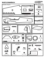
Page 4: ...Rudder 1 Wheel 2 4mm x 40mm Socket Screw 2 4mm x 16mm Machine Screw 3 AS6151 FRP Belly Pan FRP Belly Pan 1 PE0009 Hardware Set Sold in Pair 2mm Hex Nut 1 3mm x 3mm Set Screw 1 Pushrod Connector 1 Allen Wrench 1 Canopy 1 AS6152 Canopy FRP Cowl 1 AS6150 FRP Cowl Mounting Ring 1 2 3 x 12mm Wood Screw 4 Mounting Block 4 Back Plate 1 3mm x 12mm Self Tapping Screw 4 No 3278W Spinner 720 c c Tank 1 Fuel ...

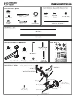
Page 5: ...ft 1 Steering Fork 1 2 6mm x 26mm Sink Head Screw 1 Tire 1 Tail Wheel 1 Plastic Washer 2 Wheel Spacer 1 2 3mm x 12mm Wood Screw 2 No 3012 Anti Vibration Engine Mount Mounting Beam 2 T Washer 8 Rubber 8 Blind Nut 4 5mm x 40 Socket Screw 4 Hex Wrench 1 Spring Washer 4 Eng Mounting Screw 6 32 x 20mm 4 4mm x 20mm 4 AS6154 Decal AS6153 Piano Wire Piano Wire 1 No 3016 2 3mm Pushrod Set Sold in Pair Dia ...

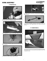
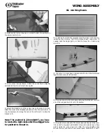
Page 6: ...e and remove covering Attach the 12 aileron extension lead to the servo Install the servo in the wing Use a servo arm instead of the standard wheel Use a piece of clear tape to temporarily hold the servo pigtail to the wing to prevent it from slipping back into the wing while you are working II Install Ailerons Remove the aileron and insertT pins into the centers of the hinges Install aileron onto...

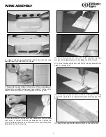
Page 7: ...ndicating the up edge Trial fit the braces in each wing panel If needed sand the edges lightly so that the brace fits in each wing smoothly Mix some 5 minute epoxy and laminate the four dihedral braces together and clamp for 30 minutes Mix up some more 5 minute epoxy and glue the dihedral brace into one of the wings and let it dry for 30 minutes Mix up an ample amount of 30 minute epoxy and apply ...

Page 8: ...s with a pen or marker Remove the plate and then remove the covering material inside the lines Be careful not to push through the balsa remove only the covering Apply a liberal amount of medium CA to the exposed wing panel and place the holddown plate on it holding it until the CA sets Turn the fuselage upside down and trial fit the wing assembly into place to insure good fit Remove the wing and w...

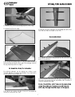
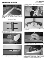
Page 9: ...ve opted for the permanent one Locate the two holes on each side of the rear of the fuselage and remove the covering film from them Insert the two carbon fiber spars into the fuselage and center them Next slide one stab onto the spars on one side Removable Stab Locate and remove the covering material from the two holes on the bottom of the stabilizers With a 1 16 drill bit drill one hole through t...

Page 10: ... pen or marker and remove the covering material inside the lines from the fuselage Mix up some 5 minute epoxy and glue the spars into the fuselage Let sit 10 minutes Mix up some 5 minute epoxy and glue the stabs to the fuselage and let sit 15 minutes Remove the elevators and rudder T pin the hinges Remove the covering from the 1 2 wide flat stip at the top rear end of the fuselage Carefully cut 1 ...

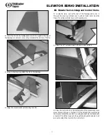
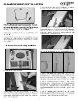
Page 11: ...at the rear of the fuselage and cut an X through the covering material over it with an Xacto knife Seal the flaps of covering material down with a sealing iron Attach the 12 extension lead to the servo and install it Place the control horn on the bottom side of the elevator and mark screw holes with a pen or marker Drill the holes all the way through the elevator Attach the control horn using the ...

Page 12: ...der and mark the holes remove the control horn and drill the holes through the rudder Attach the control horn using 2x22mm bolts On the other side of the rudder use a second control horn in place of a backing plate Thread the nuts and tighten down bolts Use a pen or marker to mark the exit hole for the pull pull cable below the stabilizer and use an Xacto to remove balsa and covering Locate the Z ...

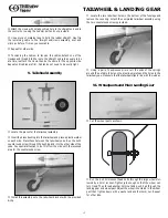
Page 13: ... sunk screw through the bushing and into the other side of the yoke Pay special attention to do this from the side with the recessed area for the countersunk screw Install this assembly onto the tailwheel bracket with the provided E clip Locate the two tailwheel holes in the bottom of the fuselage and remove the covering Attach the completed tailwheel assembly using the two countersunk screws prov...

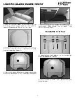
Page 14: ...owl mounting ring to the fuselage using medium CA Using 5 minute epoxy glue the cowl mounting blocks into place Be sure that the grain goes with the length of the aircraft or they will split Trial fit the landing gear cover onto the bottom of the fuselage and landing gear When satisfied with fit secure with four 2 3 x 12mm wood screw VII Install the Motor Mount Locate the motor mount hardware two ...

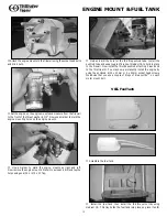
Page 15: ...s using an 6 32 or M4 x 0 7 Tap Mark and drill the hole for the throttle pushrod tube Install the pushrod tube and use a couple of drops of medium CA to hold in place in the firewall Now install the throttle pushrod attaching Z bend end to the throttle arm You may now permanently install the engine by using the enclosed 6 32 x 20mm or 4 x 20mm socket head screws We advise that you use a couple of ...

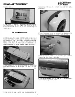
Page 16: ... to the fusalege over the area that will need to be removed from the cowl Make sure the pieces of paper are long enough to cover the cowl Tape the paper into place against the fusleage and carefully draw around the necessary areas Now using an Xacto knife cut out the drawn area Now remove the engine put the cowl into place and tape the template against the cowl Use a marker to draw inside the temp...

Page 17: ...e and cut through the covering and balsa We have placed our switch against the black trim stripe to minimize its appearance Wrap the receiver and battery pack in foam padding and place where necessary for proper balance We secured our receiver to the throttle servo tray and fitted our battery pack above the fuel tank X Wing Attachment With the fuselage upside down connect the aileron servos to the...

Page 18: ...riping tape and set aside for 24 hours XIII Prop and Spinner Install the prop We are using an APC 15x8 to go with TT PRO 120 engine Attach the spinner Depending on the prop you use you may have to modify the spinner openings XIV Control Throws These control throws are merely a starting point for your radio setup and can be tailored to fit your flying style Rudder Aileron Low Rate Aileron High Rate...

Page 19: ...have used a 1400 mAh battery pack because we are using six servos five of which are high performance servos and will draw more current than ordinary servos XVIII FlyingYour G202 140 We recommend that you take it easy on your first few flights and get a feel for your new airplane We test flew our G202 140 on low rates for the first two flights to get a feel for how it tracked and handled We also fo...

Page 20: ...uilt from balsa ply and covered with UltraCote this Almost Ready To Fly airplane is ready to load up for the field in only a few short hours Impressive scale appearance with sport performance Completely built from balsa ply and covered with UltraCote Quality epoxy fiberglass cowl is flawlessly painted Staudacher 60 ARF ACE4563 ACE4563 Staudacher Wing Span 65 Wing Area 780in2 Length 55 2 Weight 8 5...

Reviews: