3
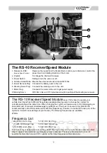
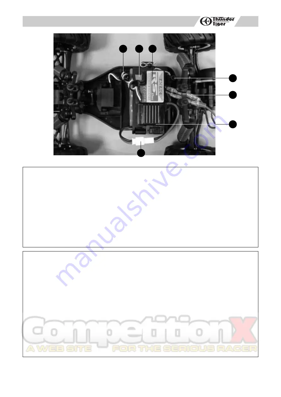
The RS-10 Receiver/Speed Module
1. Receiver & ESC:
Receives the signal from the transmitter to control your vehicle and control the
power input and rotating direction of the motor.
2. Crystal:
To change the channel it receives
3. Power Switch:
Sliding to turn the unit on or off.
4. Antenna Holder/Tube: Mounts the antenna tube as a transmitter's link.
5. Power Harness Plug: Connects the battery pack to the unit.
6. Steering Servo Plug:
Connects the steering servo to the unit.
7. Motor Plug:
Connects the motor to the unit to get power supply.
8.Steering Servo:
ACE Micro Servo C1016 provides enough to push/pull the steering servo saver.
(Electric Speed Control)
The RS-10 Receiver/Speed Module
uses 27mhz band to operate your
vehicle. Each band has 6 different frequencies available allowing users to change the crystals for
versatile operating at the same time. When changing the crystal, just replace a set of crystal plugging on
transmitter and on receiver simultaneously by pulling it out. Then push a new set of crystal into the
socket carefully on the RS module and Transmitter respectively. (Caution: do not bend the two pins of the
crystal or it would cause damage of your model.) The following frequencies are available.
27MHz
Frequency List
* 26.995 MH Brown Flag
* 27.045 MH Red Flag
* 27.0295 MH Orange Flag
* 27.145 MH Yellow Flag
* 27.195 MH Green Flag
* 27.225 MH Blue Flag
Each frequency is assigned a colored flag. Attach this flag to the end of your transmitter antenna so that
other modelers can determine your frequency from a distance. This is very important since it is not
possible for more than one model to operate on the same frequency at the same time.
2
4
5
3
5
6
1
Summary of Contents for ZT2
Page 8: ...7...


