background image

6 GENERAL 

OPERATION 


6.1 Start-up 

 
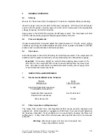
Be sure the "Hose Assembly" of paragraph 4.3 has been completed before proceeding.  
 
Insert the power cord into the ACS-1200 power receptacle.  With the ACS-1200 power 
switch in the off position, plug the power cord into an AC mains outlet of the appropriate 
voltage, frequency, and current capacity.   
 
Apply power to the ACS-1200 using the On/Off power switch.  The compressor will start 
and the outlet pressure gauge will indicate approximately 170 psiG.   
 

6.2 Pressure 

Adjustment 

 
If pressure adjustment is required adjust the output pressure to 170 psiG, during no-flow 
conditions, by turning the slotted adjustment screw on the regulator clockwise to increase 
pressure and counterclockwise to decrease pressure. 
 

6.3 Shut-down 

 
Disconnect power to the ACS-1200 using the On/Off power switch. The compressor will 
shutdown and the pressure will slowly vent as indicated by the outlet pressure gauge.   
 

Important:

  All pressure MUST be vented before applying power again to the 

ACS-1200 or the compressor will not start and will possibly blow the power input 
fuse.  All pressure must also be vented before disconnecting the air supply hose 
or severe personal injury may result. 


INSPECTION and MAINTENANCE 


7.1 

Recommended Maintenance Schedule 


 Periodic Hours 


 Maintenance 

100% Duty Cycle 


Initial Inlet/Outlet Filter Inspection 

1

st

 500 


To establish service period 


Inlet/Outlet Filter Inspection 

User Determined 


Replace when necessary 


Minor Service Kit 

15,000 


7.2 

Filter Inspection and Replacement 

 
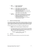
The Intake Filter, Outlet Filter, and Regulator Muffler require periodic inspection and 
replacement.  Initial inspection is suggested at 500 hours, then user should determine 
the frequency thereafter.  Most problems can be prevented by keeping the filters and 
muffler clean.  A dirty intake filter will decrease pump performance and can decrease 
pump life.   
 

Warning

: Disconnect power and be sure all pressure has 

been vented before service! 

Thunder Scientific Corporation ACS-1200 Air Compressor System 

1-6


Document Number: ACS-1200.DOC - Edition 1 - July 2005


Summary of Contents for ACS-1200

Page 1: ...Compressor System Thunder Scientific Corporation 623 Wyoming Blvd SE Albuquerque New Mexico 87123 3198 Ordering 800 872 7728 Tel 505 265 8701 FAX 505 266 6203 www thunderscientific com Copyright 2005...

Page 2: ...it to a non grounded non polarized outlet WARNING HIGH VOLTAGE is used in the operation of this equipment SEVERE INJURY OR DEATH may result if personnel fail to observe safety precautions Before worki...

Page 3: ...Meter 3 5 3 Outlet Pressure Gauge 3 5 4 Outlet Pressure Regulator 4 5 5 Air Compressor 4 5 6 Membrane Air Dryer 4 5 7 Safety Valve 4 5 8 Dimensional Drawing 4 5 9 Component Locations 5 6 GENERAL OPERA...

Page 4: ...first TSC s obligation under this warranty shall be limited to the following the Product is returned to TSC with transportation charges prepaid and that TSC s examination reveals the Product to be def...

Page 5: ...by electrocution The compressed air directly from the ACS 1200 is not safe for breathing and should never be used to supply air for human consumption The dried air from a membrane dryer will contain...

Page 6: ...sure it is a 3 wire extension cord that has a 3 blade grounding plug and a 3 slot receptacle that will accept the plug on the ACS 1200 and is 14 gauge or larger and no longer than 50 feet 5 COMPONENT...

Page 7: ...ater vapor from the compressed air stream Typical pressure dew points of 0 C or less are maintained 5 7 Safety Valve The Safety Valve mounted on compressor protects the system against pressures above...

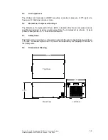
Page 8: ...F1 3 Power Cord Receptacle 9 Air Compressor COMP 4 Hour Meter HM1 10 Air Intake Filter LF1 5 Pressure Gauge G1 11 Air Dryer AD1 6 Regulator REG Rear View Rear View Left View 2 9 10 11 4 5 7 8 6 3 1 Fr...

Page 9: ...All pressure MUST be vented before applying power again to the ACS 1200 or the compressor will not start and will possibly blow the power input fuse All pressure must also be vented before disconnect...

Page 10: ...roper shutdown procedures must be followed to prevent pump damage Failure to do so may result in premature pump failure The non lubricated compressor is constructed of ferrous metals and or aluminum w...

Page 11: ...1 4 FPT PRESSURE BLEED SWEEP FILTER LF3 Figure 1 1 8 2 Electrical Schematic 123 4 POWER ENRTY MODULE PEM COMPRESSOR COMP CIRCULATION FAN CF1 HOUR METER HM1 L N G CN1 CN2 TB 1 TB 2 TB 3 TB 4 TB 5 TB 6...

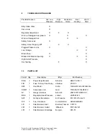
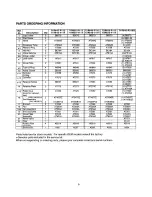
Page 12: ...Number PEM 1 Power Entry Module Schurter KM01 1205 11 FS1 1 Fuse 10 Amp Time Delay Littelfuse 218010 HM1 1 Hour Meter Curtis 700DR001048150D1002230A COMP 1 Compressor Air Gast 71R545 P315B D401X G1 1...

Page 13: ......

Page 14: ......

Page 15: ......

Page 16: ......

Page 17: ......

Page 18: ......

Page 19: ......

Page 20: ......

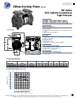
Page 21: ...ed COMMON MOTOR OPTIONS 100 100 115V 50 60 Hz single phase 220 240V 50 Hz single phase RECOMMENDED ACCESSORIES Pressure gauge Oilless Rocking Piston 2 0 cfm mm inches Product Performance Metric U S 1...

Reviews: