Page 4
For technical questions, please call 1-888-866-5797.
Item 68738
Installation
Read the ENTIRE IMPORTANT SAFETY
INFORMATION section at the beginning of
this manual including all text under
subheadings therein before set up or use
of this product:
Note:
For additional information regarding the
parts listed in the following pages, refer to the
Assembly Diagram near the end of this manual.
Identifying Port Connections
1. The battery should be connected to the ports
that show the battery icon with a + and -
symbol. Please note that “+” stands for positive
pole and “-” stands for the negative pole.
2. The DC load should be connected to the
ports that show the light bulb icon and the
positive (+) and negative (-) symbols.
3. The Solar Panel should be connected to the ports
marked with the solar panel symbol and the positive
(+) and negative (-) symbols.
WARNING!
Follow indicated polarity
for all connections and verify all
connections are secure before use.
Making Connections
WARNING!
When disconnecting or connecting,
always follow this sequence:
Disconnecting:
1. Disconnect the positive and then
negative ports of the Solar Panel.
2. Turn off the Load Switch (designated by the
bulb icon), then disconnect the load ports.
3. Disconnect the positive and then negative ports.
WARNING!
Do not disconnect battery
before disconnecting solar panel.
Connecting:
1. Connect the battery ports, first
positive and then negative.
2. Connect the solar panel ports, first
positive and then negative.
3. Connect the load ports, first
positive and then negative.
Wiring
Note:
Only a licensed electrician and a licensed building
contractor can safely design and implement a grid
tie-in system. Any grid tie-in system must meet all
applicable building and electrical codes, and must meet
standards established by the area power company.
1. Run wires from panels, through weatherproof
grommets and into enclosure where charge
controller/regulator is located. Use wires
of the proper size and rating and use twist
connectors (not included) to connect wires.
2. Secure all connections using terminals, or solder
all wire splices to ensure good connections.
3. Weatherproof all connections and route the wire in
a way that it will not be torn loose from the panel.
4. Allow system to charge according to
the solar panel’s instructions.
Operation
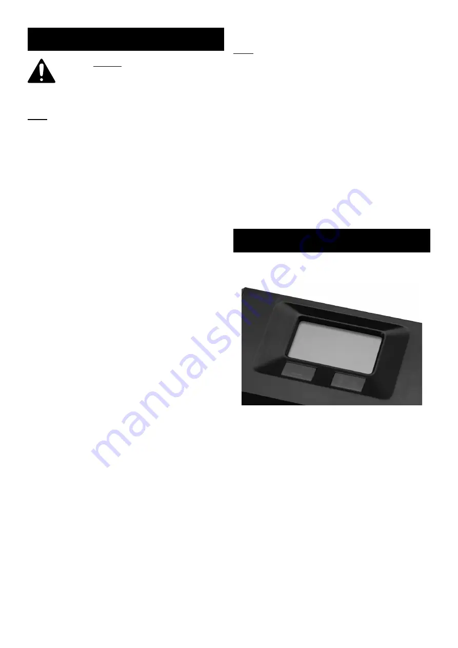
The Display Button (marked by the triangle symbol)
works in a cycle pattern. See below.
Display Button
Load Switch
By pressing the button, the LED will toggle through the
three different modes:
a. Battery Voltage (12V)
b. Output Current to Load (18A)
c. Solar Charge Current (18A)
1. Mode 1 / Battery Voltage:
The LCD will show the working voltage of the battery
(12V, for example)
Pressing the Load Switch in this mode will NOT
change the display on the LED.
2. Press the Display Button again (Mode 2) and the
LED will show the output current from battery to
load (18A).
If the Load Switch is ON, the display will not change.
If the Load Switch is OFF, the LED will show 00.0 A.


