2
REFERENCE SECTION
R1. CONNECTING AN OSCILLOSCOPE
Any conventional oscilloscope with an 8x10 division graticule can
be used with the DSA524. Only one input channel is needed and
a bandwidth of 5MHz is sufficient. The oscilloscope can be
connected using a single BNC to BNC cable. Alternatively two
cables can be used (see Appendix A).
Connect the rear panel socket marked "composite" to the vertical
input of the oscilloscope. If a two cable connection is preferred,
connect the rear panel socket marked "trigger" to the external
trigger input of the oscilloscope.
Set up the oscilloscope controls as follows:-
Vertical Input:
DC coupling
100mV per division
Timebase:
50usec per division
No Sweep Hold-off
Trigger
:
Source
— as input channel (single
cable connection)
— or external (two cable
connection)
Mode
— normal (not bright-line auto)
Coupling — AC
Slope
— negative
Level
— negative
R2. SETTING UP THE OSCILLOSCOPE DISPLAY
Switch on the DSA524 (the power switch is at the rear) and wait
while the unit performs a brief selftest and initialisation. The
oscilloscope should then show a message as follows:-
"CENTRE ARROW TIP" alternating with "THEN PRESS ESCAPE"
Adjust the oscilloscope's horizontal and vertical position controls
until the tip of the arrow is exactly in the centre of the screen.
Two horizontal lines should be visible, one at three divisions
above the graticule centre and one at three divisions below.
Pressing the ESCAPE key on the DSA524 (top right-hand corner)
will remove this set-up display and start normal operation.
Once the display oscilloscope has been set up, no further use
need be made of its controls except for occasional re-centering of
the trace to correct for any warm-up drift. To re-centre the trace
press the two keys marked "SET 'SCOPE" (on the lower right of
the DSA) and adjust the oscilloscope's position controls to centre
the arrow tip. If problems occur when setting up the display read
Appendix A.
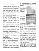
The oscilloscope setup
display.
R3. FRONT PANEL CONTROLS
All of the controls, including the rotary ones, are monitored by a
microprocessor which then performs the control. All of the
switches are of a momentary non-latching "key" type whose
status is indicated either by lamps under the panel or, where
appropriate, by text on the display. Each rotary control is enabled
or disabled by the key to its right. The control is enabled when
the lamp above the key is off, and is disabled when the lamp is
on.
The keys within the numeric keypad section (right-hand side of
unit) have up to three functions. The normal function is printed
in black above each key. After the SHIFT control is pressed the
function becomes as printed in green above the key. When a
function ending in (NN) is pressed (e.g. SAVE(NN)) the key will
enter the number printed alongside it.
Note that when SHIFT or a function ending in (NN) is pressed,
the lamp marked ENTER will flash to indicate that one or more
further key presses is required. Any function that causes the
ENTER lamp to flash can be cancelled by pressing that function
key again.
Note that some of the functions (including SET 'SCOPE)
automatically set the RUN/HOLD function to HOLD. If digitising
ceases unexpectedly check to see if you have unintentionally
set RUN/HOLD to HOLD.
All of the front panel settings are retained when the power is
turned off (except for RUN/HOLD which is always set to HOLD
at power-on).
R4. ESCAPE AND RESET
The ESCAPE key is used to terminate some of the functions of
the DSA such as "SET PLOT" and "SET AVG". At other times it
has no effect except after SHIFT has been pressed.
Pressing SHIFT followed by ESCAPE gives the RESET function.
RESET places the DSA into a known state. It cancels all of the
more complex functions and sets the DSA into a state which
makes it easy to display the input signals.
The main effect of RESET is to set up the unit as follows:-
RUN /HOLD
RUN.
CH1 and CH2
Coupling: AC, Volts/div: 1V, Offset: ZERO,
On/off: ON.
TRIGGER
Run/hold: RUN, Source: CH1, Mode: AUTO,
Level: ZERO, Slope: POS, Coupling: AC.
TRACES A
Trace A source: CH1, Trace B source: CH2,
and B
Gain variable: CAL, Position: HOME.
TIMEBASE
Time/div: 20usec.
ALL OTHER
FUNCTIONS
OFF.
After pressing RESET the DSA will be set such that the CH1
signal is displayed on trace A and the CH2 signal on trace B.
The display will be updated about three times per second. The
input sensitivity will be set at 1V per division. The timebase will
be set to 20usec/div. The input sensitivity and timebase speed
will need to be adjusted to suit the signal.
R5. CONTROLLING DIGITISING (DATA ACQUISITION)
The digitising of the input signals is controlled by the two keys
at the top of the TRIG section marked RUN/HOLD and SINGLE.
When RUN/HOLD is set to RUN, the DSA is automatically re-
armed following each acquisition. Thus digitising is repeated
continuously provided that triggering is active (see Section R9
Trigger — Mode).
When RUN/HOLD is set to HOLD, digitising is stopped and the
contents of the digitising memories is frozen. When set to
HOLD, the DSA can be armed for a single acquisition using the
SINGLE key.
Digitising
can
be
performed
on
both
input
signals
simultaneously, or on either signal individually. Each input
channel (CH1 and CH2) is enabled or disabled using the key
marked ON/OFF at the top of each channel section. When one
of the input channels is turned off, the digitising memory
associated with that channel is frozen and digitising takes place
on the other channel alone.
R6. SETTING THE TIMEBASE
The timebase of the DSA524 is somewhat different from that of
a conventional real-time oscilloscope. The time per division
keys, instead of setting a sweep speed, actually control the


