


51
NC20 - Manual - 01 - 2015
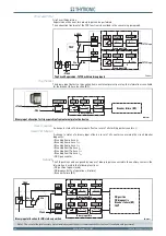
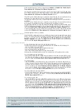
FUNCTION CHARACTERISTICS
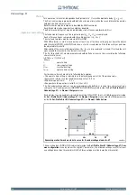
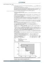
The fi rst threshold trip (
U
<) may be inhibited by start of the second threshold (
U
<<) by setting
ON
the U< Disabling by U<< start (
U<disbyU<<
) parameter available inside the
Set \ Profi le A(or B) \
Undervoltage-27 \ U<< Element \ Setpoints
.
All undervoltage elements can produce the Breaker Failure output if the
U< BF
and
U<< BF
pa-
rameters are set to
ON.
The parameters are available inside the
Set\Profi le A(or B)\Undervoltage - 27 \
U< Element
(
U<<
Element) \Setpoints
menus.
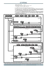
[1]
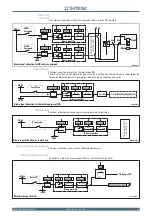
All the named parameters can be set separately for
Profi le A
and
Profi le B
(
Set\Profi le A(or B)\Un-
dervoltage - 27 \
U< Element
(
U<< Element) \Setpoints
menus).
Note 1 The common settings concerning the Breaker failure protection are adjustable inside the
Breaker Failure - BF
menu.
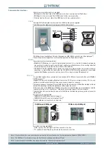
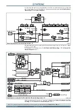
all-F27.ai
U
MMI
U<< Element
Disable 27 elements
Start U<<
Start U<<
Start U<
Trip U<
Trip U<<
&
≥
U< disbyU<<
U< inhibition
U<< inhibition
t
U< def
t
U< inv
U<
def
t
U<< def
U<<
def
U<
inv
U< Curve
U< Enable
State
Block1
BLK1U<
&
U<BLK1
Start U<
&
Block1
BLK1U<<
&
U<<BLK1
Start U<<
&
U<BF
Trip U<
&
U<BF
U
AND
U
U
L1
,
U
L2
,
U
L3
OR
Common configuration
Logic27
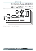
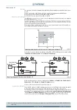
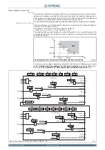
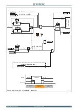
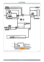
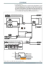
General logic diagram of the undervoltage elements - 27
all-F27.ai
U
MMI
U<< Element
Disable 27 elements
Start U<<
Start U<<
Start U<
Trip U<
Trip U<<
&
≥
U< disbyU<<
U< inhibition
U<< inhibition
t
U< def
t
U< inv
U<
def
t
U<< def
U<<
def
U<
inv
U< Curve
U< Enable
State
Block1
BLK1U<
&
U<BLK1
Start U<
&
Block1
BLK1U<<
&
U<<BLK1
Start U<<
&
U<BF
Trip U<
&
U<BF
U
AND
U
U
L1
,
U
L2
,
U
L3
OR
Common configuration
Logic27
General logic diagram of the undervoltage elements - 27
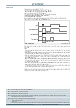
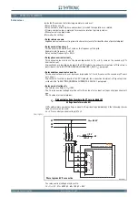
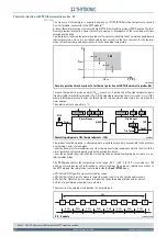
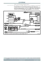
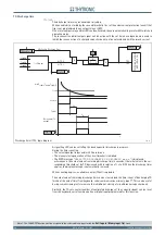
Fun-F27_S1.ai
Logic diagram concerning the first threshold (U<) of the undervoltage element - 27
U< Inhibition
(ON
≡
Inhibit)
&
U
< Curve
0
T
RESET
t
U<
0
T
TRIP
P
ING
M
A
TRIX
(LED
+R
EL
A
Y
S
)
t
U<def
t
U<inv
Start U<
U<ST-K
Start U<
U<TR-K
U<ST-L
U<TR-L
Trip U<
Trip U<
Trip U<
BF Enable (ON
≡
Enable)
U<BF
towards BF logic
&
BLK1U<
U< BF
&
&
&
Enable (ON
≡
Enable)
Block1 input (ON
≡
Block)
U<BLK1
Block1
Block1
Logic27
≥1
&
U
L1
U
L2
U
L3
Binary input INx
T
0
Logic
INx
t
ON
INx
t
ON
INx
t
OFF
T
0
n.o.
n.c.
INx
t
OFF
≥
1
&
State
U
<
inv
U
≤
U<
def
U
≤
U<
inv
U
<
def
&
State
ON
≡
Enable U< undervoltage element
U< Enable
27 Inhibition
(ON
≡
Inhibit)
by MMI
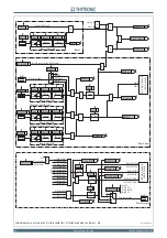
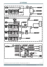
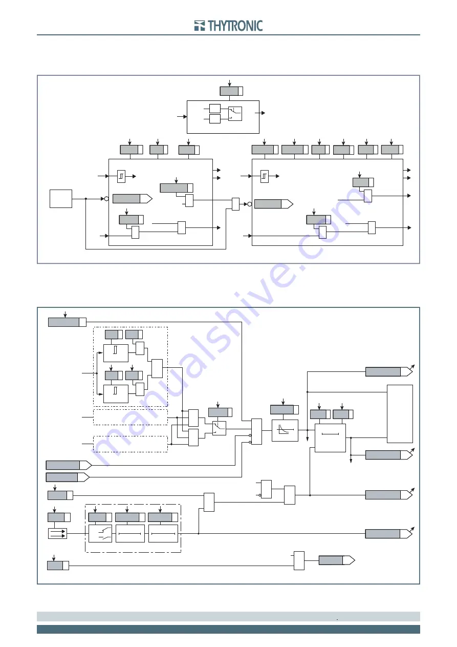


