18
NVA100X-D - Manual - 02 - 2016
TECHNICAL DATA
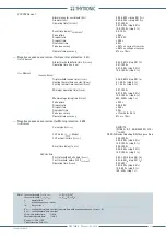
Output relays
Minimum pulse width
0.000...0.500 s (step 0.005 s)
Logic
De-energized/Energized
Operating mode
Latched/No latched
Input sequence
Side H phase current sequence (
I-SequenceH
)
IL1-IL2-IL3,
IL1-IL3-IL2....
Side L phase current sequence (
I-SequenceL
)
IL1-IL2-IL3,
IL1-IL3-IL2....
Phase voltage sequence (
U-Sequence
)
UL1-UL2-UL3,
UL1-UL3-UL2,....
Polarity
A1-A2 Terminals polarity (A1-A2 POL)
NORMAL/REVERSE
A3-A4 Terminals polarity (A3-A4 POL)
NORMAL/REVERSE
A5-A6 Terminals polarity (A5-A6 POL)
NORMAL/REVERSE
A7-A8 Terminals polarity (A7-A8 POL)
NORMAL/REVERSE
B3-B4 Terminals polarity (B3-B4 POL)
NORMAL/REVERSE
B5-B6 Terminals polarity (B5-B6 POL)
NORMAL/REVERSE
B7-B8 Terminals polarity (B7-B8 POL)
NORMAL/REVERSE
B9-B10 Terminals polarity (B9-B10 POL)
NORMAL/REVERSE
C1-C2 Terminals polarity (C1-C POL)
NORMAL/REVERSE
C3-C4 Terminals polarity (C3-C POL)
NORMAL/REVERSE
C5-C6 Terminals polarity (C5-C6 POL)
NORMAL/REVERSE
C7-C8 Terminals polarity (C7-C8 POL)
NORMAL/REVERSE
Starting control set
CLP input source (
CLP Source
)
IRUN/CB
IRUN Threshold (
I
RUN
)
0.10
I
B
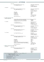
3.7 PROTECTIVE
FUNCTIONS
Base current - IB
Base current (
I
B
)
[1]
0.10...2.50
I
n
(step 0.01
I
n
)
Underimpedance - 21
Z< Element
Defi nite time
First threshold defi nite time (
Z
<
def
)
0.02...3.00
Z
n
[2]
(step 0.01
Z
n
)
Operate time (
t
Zdef
<)
0.07...100.0
s
0.07...9.99 s (step 0.01 s)
10.0...100.0 s (step 0.1 s)
Reset time delay (
t
Z
<
RES
)
0.00...100.0
s
0.00...9.99 s (step 0.01 s)
10.0...100.0 s (step 0.1 s)
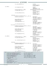
Z<< Element
Defi nite time
Second threshold defi nite time (
Z
<<
def
)
0.02...3.00
Z
n
[2]
(step 0.01
Z
n
)
Operate time (
t
Zdef
<<)
0.07...100.0
s
0.07...9.99 s (step 0.01 s)
10.0...100.0 s (step 0.1 s)
Reset time delay (
t
Z
<<
RES
)
0.00...100.0
s
0.00...9.99 s (step 0.01 s)
10.0...100.0 s (step 0.1 s)
Pickup
time
≤
0.04
s
Dropout
ratio
1.03...1.05
Dropout time
≤ 0.05 s
Overshoot
time
0.03
s
Reference
values
rest:
1.5
I
T
trip:
0.5
I
T
[3]
Pickup
accuracy ±
4% ±
0.5%
Z
n
Operate time accuracy
5% or ± 10 ms
Nota 1 The base current I
B
represents the rated current of the line or transformer, referred to the nominal current of the CT’s for thermal image protection.
Note 2 Zn is the impedance given by the ratio between the relay rated voltage relay (U
n
) and the rated current of the relay (I
n
) Z
n
= U
n
/I
n
Nota 3 I
T
is the value of input current required to trip for a given threshold setting and for a given input voltage (eg with setting Z<= 1.00 Z
n
and input
voltage 1.00 U
n
, the reference value I
T
is 1.00 I
n
)
—
—
—
—
—
—
—


