234
NVA100X-D - Manual - 02 - 2016
FUNCTION CHARACTERISTICS
w side. It expresses the compensation which the current displacements are corrected so that they
are in-phase (zero phase shift) with currents on the reference side and possibly fi ltered by the zero
sequence components.
It allows sw correction of the phase currents displacement on the sides of the transformer due to
the transformer vector group, any phases reversal of cyclic sequence and the elimination of any zero
sequence components that may occur on some sides as a result of connection of the windings of the
transformer and its ground against ground faults outside the zone of differential protection.
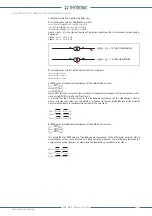
MatchType=ESTERNAL
If inside the
Set \ Base
menu the
MatchType=ESTERNAL
parameter is set (compensation with
external CTs), then C(w) is the identity matrix:
MatchType=INTERNAL
If inside the
Set \ Base
menu the
MatchType=INTERNAL
parameter is set then the C(w) matrix is
defi ned by relay as:
Calculation of the displacement of phase currents of each side concerning the H-side, from the
VectGroup(H)
e
VectGroup(L
) programming parameters in the
Set \ Transformer
menu:
I
(H)
= VectGroup
(H)
∙ 30° = 0
Current displacement on side H
I
(L)
= [VectGroup
(H)
- VectGroup
(L)
] ∙ 30°
Current displacement on side L
Side of reference choice for the current phase compensation programming parameters from
Conn(H)
and
Conn(L)
parameters inside the
Set \ Transformer
menu: the delta winding (D or d
programming) or zig-zag (Z or z programming) side is the reference side. If more than one winding
is delta connected or zig-zag, or if no winding is connected delta or zig-zag as the reference is
chosen to side with the index H.
The relay calculates the angle of compensation phase for each side
)
c(H),
)
c(L) through the
reference side for the phase compensation of point B) above, through the current phase shifts
calculated in paragraph A) above setting and through the setting of the
I-sequenceH
parameter
for side H and
I-sequenceL
for side L available inside the
Set \ Input sequence
menu . The cal-
culation is done as shown in the following table.
Reference side
for phase compensation
Phase Cyclic sequence
(I-sequence)
Phase compensation angles
)
c(w)
H
I-sequenceH L1, L2, L3
)
c
(H)
=
I
(H)
-
I
(H)
= 0
)
c(L) =
I
(H)
-
I
(L)
= 0
I-sequenceH L1, L3, L2
)
c
(H)
=
I
(H)
-
I
(H)
= 0
)
c
(L)
=
I
(L)
-
I
(H)
= 0
L
I-sequenceL L1, L2, L3
)
c
(H)
=
I
(L)
-
I
(H)
= 0
)
c
(L)
=
I
(L)
-
I
(L)
= 0
I-sequenceL L1, L3, L2
)
c
(H)
=
I
(H)
-
I
(L)
= 0
)
c
(L)
=
I
(L)
-
I
(L)
= 0
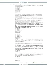
Depending on the compensation angles referred to in paragraph C), on the
Gnd(w)
parameter
setting available inside the
Set \ Transformer
menu, the relay considers the phase compensation
matrix C (w) the cyclic sequence mode and zero-sequence current of side w = H, L as shown in
the following tables.
A)
B)
C)
D)
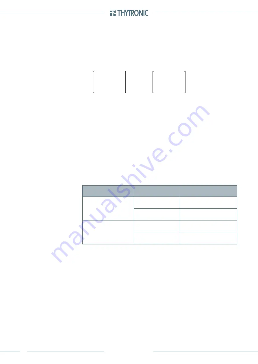
C
(H)
= 0 1 0
1
0 0
0 0 1
C
(L)
= 0 1 0
1
0 0
0 0 1


