FUNCTION CHARACTERISTICS
105
NVA100X-D - Manual - 02 - 2016
Negative sequence overcurrent for Generator protection - 46G
Preface
The machine may operate with an unbalanced load due to single-phase or non-linear loads, the trip-
ping of fuses, line interruption in one phase, asymmetric faults, tripping and unipolar reclosing on the
transmission lines.
Application
Protection of synchronous generators and motors. The unbalanced load creates a stator magnetic
fi eld rotating contrariwise to the direction of rotation, which hence corresponds to a magnetic fi eld
rotating at twice the speed with respect to the rotor. Hence, currents are induced at twice the fre-
quency in the rotor magnetic circuit (parasitic currents), the fi eld windings and the damper windings,
responsible for increased loss of iron and copper and hence overheating of the machine.
The unbalanced load protective device estimates the inverse sequence current
I
2
from the phase
current readings on side L: it makes use of an a adjustable (
I
2AL
>) and delayed (
t
2AL
>) time indepen-
dent alarm threshold and a thermal trip threshold with constant
I
2
2
t characteristics, developed so
as to optimally coordinate with the inverse sequence current limits which may be tolerated perma-
nently and for brief periods for each type of machine.
The thermal characteristic of the protective device is:
t
=
K
heat
/(
I
2
/
I
B
)
2
where
t
is the trip time, mea-
sured from the point of exceeding the adjustable threshold
I
2
>>,
K
heat
is the machine thermal time
constant at the inverse sequence current and
I
B
is the base current.
When the inverse sequence current
I
2
drops below the threshold
I
2
>>, the protective element resets
after an adjustable time delay
K
cool
/(
I
2
>>/
I
B
)
2
wherw
Kcool is the cooling time constant of the pro-
tected machine at the inverse sequence current.
Operation and settings
The negative sequence current is computed as:
I
2
=(
I
L1L
+e-
j120°
·
I
L2L
+e
+j120°
·
I
L3L
)/3
where e
-j120°
=-1/2-j√3/2, e
j120°
=-1/2+j√3/2.
The negative sequence current is compared with the alarm setting value (
I
2AL
>); currents above the
associated pickup value are detected and a start is issued and after expiry of the associated operate
time (
t
2AL
>, defi nite time) a trip command is issued; if instead the current drops below the threshold,
the element it restored.
The second threshold (
I
2
>>) inverse time according the
I
2
2
t characteristic curve:
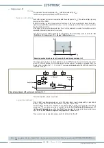
I-squared-t (
I
2
t = K):
t
=
K
heat
/(
I
2
/
I
B
)
2
(with
I
2
≥
I
2
>>)
Where:
t
: operate
time
(
t
2min
≤
t
≤
t
2max
)
K
heat
thermal time constant
I
B
base current
[1]
Note 1 Assuming that the secondary rated current of the line CT’s equals the rated current of the NG20 relay, as usually happens, the IB value is the
ratio between the rated current of the protected component (motor or generator) and the primary rated current of the CT’s Inp
—
•
t-int-F46.ai
I
2
/
I
B
I
2
>>
t
2 max
t
2 min
t
2 A L
>
I
2 A L
>
t
General operation characteristic for the negative sequence overcurrent element - 46G
TRIP
t-int-F46.ai
I
2
/
I
B
I
2
>>
t
2 max
t
2 min
t
2 A L
>
I
2 A L
>
t
General operation characteristic for the negative sequence overcurrent element - 46G
TRIP


