FUNCTION CHARACTERISTICS
255
NVA100X-D - Manual - 02 - 2016
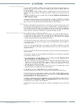
Internal selective block -BLOCK4
As well as to send or transmit a selective block toward other protective relays, each protective
element may be enabled for receive or transmit a selective block from/to other internal protective
elements.
The internal selective block of one or more element may be enabled/disabled by means the
Ixxx-
BLK4
parameters (virtual input and output common to all protective thresholds); the following oper-
ating modes are available:
IN - the element is enabled to receive the selective block from an internal input.
OUT - the element is enabled to send the selective block to an internal output.
OFF - the element is disabled to send/receive the internal selective block.
Transmission and reception for the same element is not allowed, so any stall situation due to wrong
setting is avoided.
The internal selective block can work together with an external selective block from other protective
relays (Block2 input and Block2 output).
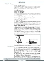
For any element the logic state of the internal output block and the trip state are defi ned by:
Start threshold
Internal selective logic block
according to the following table.
START threshold
xxx
IxxxBK4=IN
IxxxBLK4=OUT
xxx TRIP
threshold
SELECTIVE BLOCK
xxx
threshold
0
0
0
0
0
0
1
0
0
0
1
0
1 within
t
FI-Iph
1 after the operate time
0
1
1
1 within
t
FI-Iph
1
0
If the xxx threshold is started, regardless of the internal input and output, the element is always
OFF (no trip).
If the xxx threshold start stay ON within the operating time and the internal input is OFF, when the
timer expires the trip goes ON.
If the xxx threshold is started and the internal input is ON, the xxx threshold is blocked (the operat-
ing timer is forced to reset); the element is OFF (no trip).
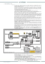
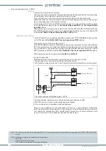
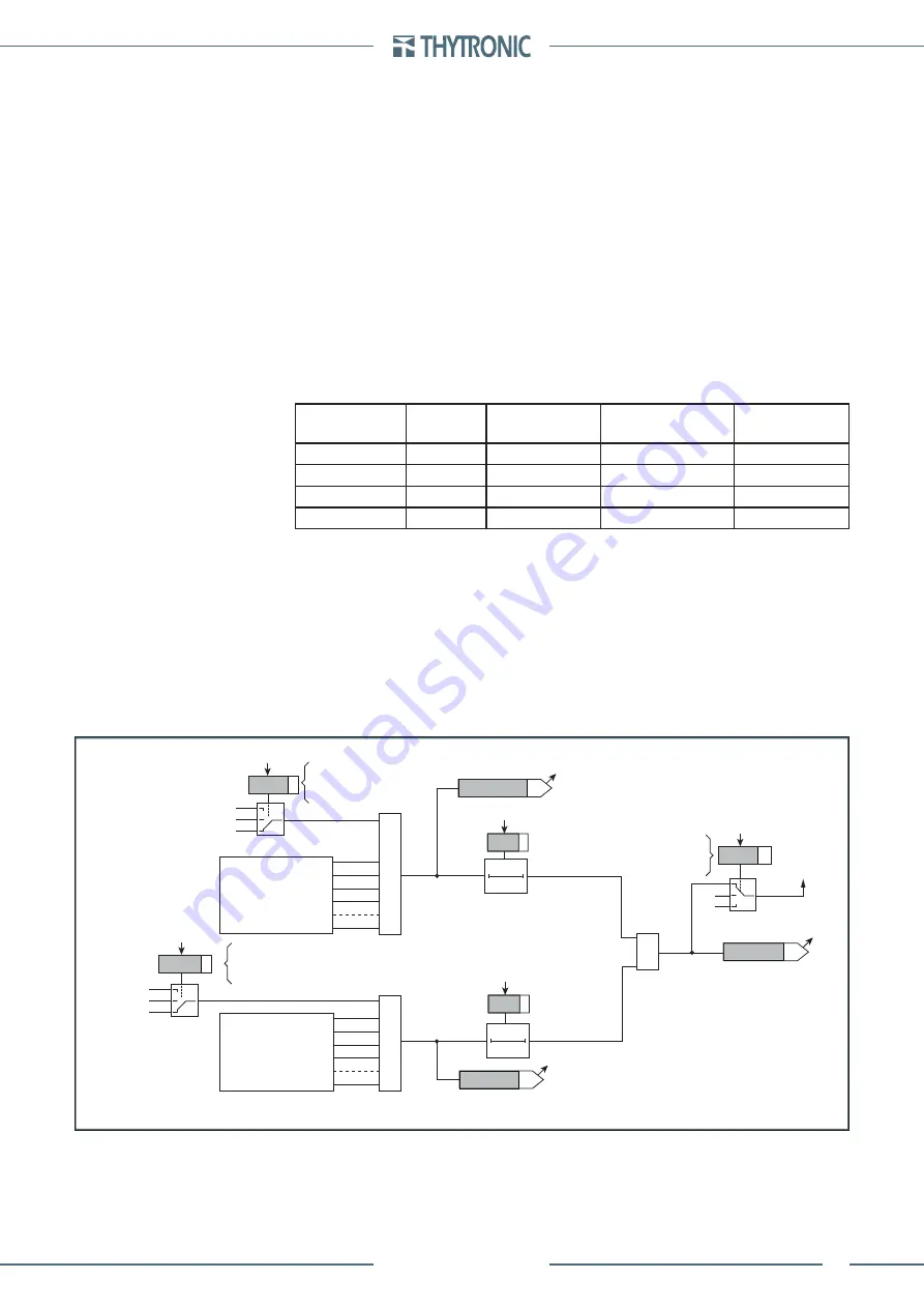
The internal selective block output goes ON when the threshold is started and stays ON (despite the
start goes OFF) along an adjustable time
t
FI-Iph
common for all phase elements 50-51-67 or
t
FI-IE
com-
mon for all earth elements 50N-51N-67N.
The
t
FI-IPh
and
t
FI-IE
counters start when the output selective block becomes active; when the coun-
ters expire the internal block selective output is forced OFF (despite the start xxx remain active).
If the
t
FI-IPh
,
t
FI-IE
e
t
FI-IPh/IE
timers are cleared the selective block output state is freeze up to the
start xxx remain active.
With a setting other than 0.00 s, the
t
FI-IPh
,
t
FI-IE
e
t
FI-IPh/IE
timers may be used to have a backup pro-
tection available against breaker failure inside a selectivity logic system, as well as to hold blocked
upstream protective relay up to your own reset
.
—
•
•
•
•
•
•
•
•
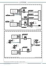
Block4-in-out-diagram.ai
t
FI-Iph
ST-IE BLK4
ST-Iph BLK4
≥
1
t
FI-IE
Block4 OUT
T
0
t
FI-Iph
T
0
t
FI-IE
xx
Block4 OUT
Block4
A = IN
B = OFF
C = OUT
B
C
“0”
“0”
I
E
> Block4 I/O
A = IN
B = OFF
C = OUT
I
E
>BLK4
Start
I
E
>
C
B
A
“0”
“0”
xxBLK4
A
Logic diagram concerning the output signals of the internal selective block function - Block4
I>BLK4
Start
I>
Block4 enable
I>
Block4 I/O
A = IN
B = OFF
C = OUT
C
B
A
“0”
“0”
All other BLK4 I/O
of phase elements
≥
1
All other BLK4 I/O
of ground elements
≥
1

