268
NVA100X-D - Manual - 02 - 2016
FUNCTION CHARACTERISTICS
VT supervision - 74VT
Preface
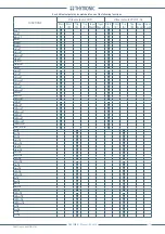
The protection is available in all versions.
The VT monitoring function is employed to issue an alarm when secondary phase VTs and/or phase in-
put failure are detected; typical faults are internal faults, fuse failure, fault on the interconnecting wires
or MCB tripping. The function gives an alarm indication and change automatically all the protection
elements (27, 67 e 67N) that can output misoperations when a voltage failure is detected.
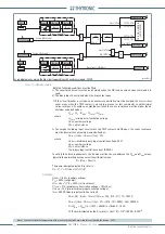
The following VTs anomalies are detected:
Loss of one or two phase voltages
Loss of all three phase voltages
No voltage detected upon energisation.
Loss of one or two phase voltages
This fault is detected when a negative sequence voltage without presence of negative sequence
current is detected. When the negative sequence voltage exceeds the adjustable threshold (
U
2VT
>)
and the negative sequence current is lower than an adjustable threshold (
I
2VT
>), an output relay
and/or LED can be activated.
The negative sequence current is calculated according the following:
I
2
= (
I
⃗
L1
+e
-j120°
I
⃗
L2
+e
+j120°
I
⃗
L3
)/3
Similarly the negative sequence voltage is calculated according the following:
U
2
= (
U
⃗
L1
+e
-j120°
U
⃗
L2
+e
+j120°
U
⃗
L3
)/3,
where e
-j120°
= -1/2 - j√3/2 e e
+j120°
= -1/2 + j√3/2
Loss of all three phase voltages
If a collapse of the three phase voltage without a corresponding change on the phase current is
detected a VT failure is detected.
When all three voltages drop down the adjustable threshold (
U
VT
<) and the present value of three
phase currents (
I
L1(k)
,
I
L2(k)
,
I
L3(k)
) and the same currents one cycle previously (
I
L1(k-1)
,
I
L2(k-1)
,
I
L3(k-1)
)
don’t move away from an adjustable threshold (
Δ
I
VT
<), an output relay and/or LED can be activated.
No voltage detected upon energisation
The lack of three phase voltage after line energisation is detected if the circuit breaker is closed and
all the three phase voltages (
U
L1
,
U
L2
,
U
L3
) are lower than an adjustable threshold (
U
VT
<) and all the
three phase currents (
I
L1
,
I
L2
,
I
L3
) are lower than an adjustable threshold (
I
VT
>); the latter must be
adjusted to a value higher than the current at energisation and lower than the short circuit current.
When any of the previous condition is detected, the 74VT function issues a blocking command or
switches to non directional the 67 and 67N protective elements; after an adjustable delay (
t
VT-AL
) an
output alarm is activated.
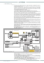
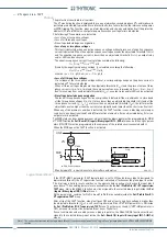
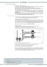
The MCB state can be acquired by means a binary input; the binary input must be programmed for
MCB
VT OPEN
inside the
Set \ Board 1(2) inputs \ Binary input IN1-1...(IN1-x)
menus. and the
Logic
param-
eters (
ON/OFF
) must be programmed in the same way of the related circuit connected with-it.
When the MCB opens the 74VT function is activated.
Logical block (Block1)
If the
74VT-BLK1
parameter (74VT logical block) is set to
ON
, and a binary input is designed for
logical block (Block1), the VT supervision function is blocked off whenever the given input is active.
The trip timer is held in reset condition, so the operate time counting starts when the input block
goes down.
[1]
The enabling parameter are available inside the
Set \ Profi le A(or B) \ VT supervision-
74VT
menu, while the
Block1
function must be assigned to the selected binary input inside the
Set
\ Inputs \ Binary input IN1-1 (INx-x)
menus.
All the parameters, common for Profi le A and Profi le B are available inside the
Set \ Profi le A(or B) \
VT supervision-74VT
menu.
After a trip of the 74VT function, when fault goes OFF and at least one phase voltage is higher than
the adjustable threshold (
U
VT
<), a self reset is performed if the
74VT-AR
parameter is ON inside
the
Set \ Profi le A(or B) \ VT supervision -74VT
menu. The other way round, (
74VT-AR
parameter is
OFF), a manual reset must be activated (Front key or ThySetter).
A reset command can be send by means a binary input also; the
Reset LEDs
function must be as-
signed to the selected binary input inside the
Set \ Board 1(2) inputs \ Binary input IN1-1...(IN1-x)
menus.
Note 1 The exhaustive treatment of the logic block (Block 1) function may be found in the “Logic Block” paragraph inside
CONTROL AND MONITORING
section
—
•
•
•
•
•
•
MCB-VT.ai
VTs
LINE
MCB
to PRO_N voltage inputs
BINARY INPUT
Pro_N
U
AUX
Monitoraggio TV - acquisizione stato interruttore automatico
MCB VT OPEN
MCB VT OPEN

