22222
RMT3\08
09-2000
MODALITÀ PER L'INSTALLAZIONE
MODALITÀ PER L'INSTALLAZIONE
MODALITÀ PER L'INSTALLAZIONE
MODALITÀ PER L'INSTALLAZIONE
MODALITÀ PER L'INSTALLAZIONE
INSTALLATION MODALITY
INSTALLATION MODALITY
INSTALLATION MODALITY
INSTALLATION MODALITY
INSTALLATION MODALITY
Montaggio meccanico
Montaggio meccanico
Montaggio meccanico
Montaggio meccanico
Montaggio meccanico
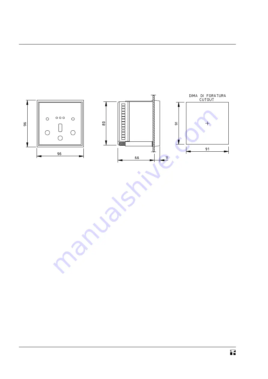
I dispositivi RMT/3 sono adatti per montaggio incassato; le
dimensioni d'ingombro son conformi alle norme DIN.
Le dimensioni sono indicate nel disegno sottoriportato.
I trasformatori toroidali sono dotati di staffa per montaggio a
sbalzo su pannello.
Mechanical mounting
Mechanical mounting
Mechanical mounting
Mechanical mounting
Mechanical mounting
The devices RMT/3 are designed for flush mounting; their
dimensions are in accordancewith DINstandards.
Dimensions are indicated in the drawing below.
The toroidal transformers are provided with a bracket for a
projecting mounting onto wall.
Collegamenti elettrici
Collegamenti elettrici
Collegamenti elettrici
Collegamenti elettrici
Collegamenti elettrici
I collegamenti elettrici devono essere eseguiti in conformità allo
schema d'inserzione rappresentato nella pagina seguente.
CIRCUITO DI ALIMENTAZIONE AUSILIARIA
Il relè necessita di una tensione ausiliaria ai morsetti 1-2-3 , come
indicato sull'apparecchio stesso. In caso di alimentazione in corrente
continua, la tensione deve essere derivata da una batteria o da un
raddrizzatore trifase con ondulazione massima del 15%. In caso di
alimentazione in corrente alternata, la tensione può essere derivata
dalla stessa rete controllata, a monte del contattore o dell'interruttore
automatico associato al dispositivo RMT/3, per assicurare la pre-
senza di tensione al circuito di alimentazione ausiliaria.
Il dispositivo può funzionare con una tensione ausiliaria avente
una tolleranza di ±20 % rispetto al valore nominale indicato in targa,
(±10 % per versione 24-48V-).
CIRCUITO AMPEROMETRICO
Ai morsetti 13-14 sono collegati i conduttori provenienti dai
morsetti di misura del trasformatore toroidale, identificati con S1-
S2.
La sezione dei conduttori deve essere non inferiore a 1 mm
2
e di
lunghezza la più breve possibile (massimo 20 m). I conduttori non
devono essere installati in prossimità di componenti elettromeccanici
o di conduttori di potenza, i quali possono essere fonte di campi
magnetici e di perturbazioni transitorie del segnale misurato. In caso
di elevate induzioni, i conduttori amperometrici devono essere
avvolti tra loro ed eventualmente in esecuzione schermata, avendo
cura di collegare lo schermo al morsetto 11.
CIRCUITO DI RIPRISTINO
Il relè amperometrico è previsto con il pulsante di ripristino
manuale RESET posto sul fronte della custodia; il comando di
ripristino può anche essere rinviato a distanza collegando un pulsan-
te normalmente aperto ai morsetti11-12. Per i due conduttori relativi
al comando di ripristino devono essere osservate le medesime
raccomandazioni indicate per il circuito amperometrico.
Electrical connection
Electrical connection
Electrical connection
Electrical connection
Electrical connection
Electrical connections must be made according to the diagram
indicated in the following page.
AUXILIARY SUPPLY CIRCUIT
The measuring device requires an auxiliary voltage be applied at
terminals 1-2-3, as indicated on the case. If the supply is direct current,
the voltage must be derived from a battery or a three-phase bridge
rectifier with a maximum residual ripple of 15%. If the supply is
alternating current, the voltage can be derived from the same line where
the device is installed, with a connection above the contactor or the
circuit breaker controlled by RMT/3: in this way the supply to the
circuit is assured even upon operation of the device RMT/3.
The device can work with an auxiliary voltage having a tolerance
of ±20 % with respect to the nominal value indicated on the case, (±10
% for 24-48V-).
CURRENT CIRCUIT
The measuring terminals of the toroidal transformer, indicated
with S1-S2, must be connected to terminals 13-14 of the measuring
relay.
The cross section of the conductors must be not lower than
1 mm
2
and their lenght as short as possible (20 m maximum). These
conductors must not run close to electromechanical components or
power cables, wich can give rise to magnetic fields or transient
disturbances affecting the measured signal. In the worst conditions
of high magnetic induction, the signal conductors must be twisted
together and possibly shielded, by connecting the shield to
terminal 11.
RESET CIRCUIT
The current measuring relay is provided with a manual RESET
pushbutton located on the front plate; the reset control can also be
remotely operated by connecting a normally open pushbutton to
terminals 11-12. The same recommendations above indicated for the
current circuit also apply for the external reset circuit connection.


