102
FUNCTION CHARACTERISTICS
—
100% stator earth-fault with 3rd harmonic: residual under-overvoltage (27H-59H)
Preface
The protective device, used in conjunction with the 90% stator ground (50G/51G or 59N) protective
element, extends protection against breakdown of the insulation towards the generator stator win-
dings earth to 100%.
The element measures the residual voltage third harmonic component
U
E3H
, due to the non linearity
effect of the magnetic circuit.
The operational logic may be programmed as third harmonic Undervoltage (27H) protection, when
measurement is performed by VT or transformer of the machine star point, or third harmonic Over-
voltage (59H), when measurement is performed using VT with open triangle secondary on the gene-
rator line side.
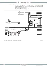
In both methods, the protective device makes use of a settable (UE3H< for the 27H protective device
or UE3H> for 59H) and delayed (tUE3H< or tUE3H>) trip threshold with definite time trip characteristic.
The device is enabled within the 20...75 Hz frequency range.
The element may be associated with the breaker failure (BF) function.
The protective element logical block may be programmed using a logical input in order to avoid
tripping when the generator is shutting down.
Alternatively, inhibition of the protective element with the generator stopped may be obtained by
programming a Undervoltage supervision: in this case, the 100% stator ground protective function
is inhibited when all three phase to phase voltages measured by the line VT fall below an adjustable
threshold (UIN-3H< ).
Inhibition of the protective function may also be programmed when all three phase currents drop
below an adjustable threshold (IIN-3H< ), to prevent tripping with reduced load generators and any
third harmonic voltage. This inhibition is deactivated by tripping of the CT monitoring function (74CT).
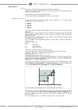
Depending on the placement of the TV, the protection can be programmed as the minimal (27H) or
maximum third harmonic voltage (59H);
[1]
this should be set to
Maximum
or
Minimum
the
UE3H
parameter
mode
available inside the
100% stator earth-fault with 3rd harmonic - 27H-59H \ 1st
Pickup Element \ Setpoint
menu.
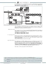
Residual voltage measured by TV or on the transformer star point
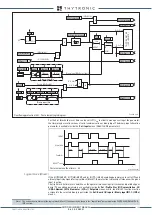
The trend of third harmonic residual voltage across the stator winding is shown in figure for three
different positions of fault and without faul.
The operating logic must be programmed as low voltage third harmonic (27H) protection of in order
to detect the reduction of the value of third harmonic component of residual voltage present in nor-
mal operation, in the case of earth fault in the near star center.
If a fault occurs near the generator terminals, the third harmonic component is increased and conse-
quently the elimination of the fault lies with the residual overvoltage element where the fundamental
component is measured; its pattern is shown in Figure to highlight the criterion of overlapping regu-
lations, useful to obtain complete protection of stator winding (100%).
[2]
Operation and settings
Note 1 The undervoltage and overvoltage protections are alternatives and the choice should be based on the positioning of the VT transformers.
Note 2 The scale used for the fundamental component is different from that used for the third harmonic.
3rd-har-star.ai
Evolution of fundamental and third harmonic components of residual voltage
along the stator winding, measured by means of VT star point
third harmonic component
without fault
fundamental component of the
residual voltage without fault
3rd harmonic minimum
voltage threshold
U
E3H
<
U
E3H
before
failure
third harmonic component
in the presence of earth fault
in the star center
third harmonic component
in the presence of earth fault inlimit
point detectable by 27H
third harmonic component
with earth fault on terminals
fundamental component of the
residual voltage with earth fault
along the winding
59N threshold,
U
E
> or
U
E
>>
27H
59N
27H
59N
100%
100%
0
0
XMR-D EQUIPMENT MANUAL
Ed. 2.9 - 02/2021


