146
FUNCTION CHARACTERISTICS
—
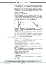
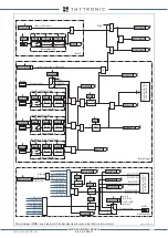
Thermal image - 49LT for Line or Transformer protection (Side H and Side L)
Preface
It is a overload protection with memory capability and three setpoints, used to protect lines and
transformers against thermal overload.
The phase currents are used into an algorithm reproducing a thermal replica according the IEC
60255-8 standard taking into account the Joule losses and the cooling effect due to the load re-
duction; in this way the previous history and the overload are taken into account.
The thermal protection can be adapted to the different features of motors by setting the thermal
heating t+ and cooling t- constants ( the t+ constant refers to motor running condition, while the
t- constant, always higher than t+, refers to stop condition).
The trip element has an adjustable threshold; with 1.2 D
q
B
setting (ie 1.2 times the overtemperature
corresponding to the nominal operation condition) the corresponding tripping current
I
B
is 1.1 since
the temperature rise is proportional to the square of the current.
The 49 element is provided with two further thresholds D
q
AL1
and D
q
AL2
, lower than the previous one.
These thresholds, both adjustable, provide an alarm signal to draw attention in the event of anoma-
lous heating, without disconnect the protected device. One of the above thresholds can be used to
prevent refeeding of the system when heating approaches the trip conditions since the additional
heating brought on by the inrush currents would cause the protection to operate.
Operation and settings
The thermal current used for thermal image calculation is:
I
th
= max (
I
L1
,
I
L2
,
I
L3
)
If the second harmonic restraint is enabled, the thermal current used for thermal image calculation
becomes:
Ith =
I
LMAX
/
K
INR
= max (
I
L1
,
I
L2
,
I
L3
) /
K
INR
where
K
INR
is an adjustable parameter (1.0...3.0), useful to reduce the thermal current during the
transformer energization (inrush).
According to a single-body thermal model, the thermal image is based on the differential equation:
dD
q
/dt+D
q
/T=(
I
th
/
I
B
)
2
/T
where D
q
is the system thermal state as a percentage of base thermal capacity D
q
B
corresponding
to the base current
I
B
1
and T is the thermal time constant (the same for heating and cooling).
When the thermal image D
q
overcomes the threshold D
q
> a trip is issued.
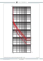
The operating characteristic (IEC 60255-8) is:
t
=T*ln{[(
I
th
/
I
B
)
2
-D
q
p
/D
q
B
)]/[(
I
th
/
I
B
)
2
-1.2]}=T*ln{[(
I
th
/
I
B
)
2
-(
I
p
/
I
B
)
2
]/[(
I
th
/
I
B
)
2
-1.2]=
T*ln{[(
I
th
/
I
B
)
2
-
p
2
]/[(
I
th
/
I
B
)
2
-1.2]} [1]
where:
• t:
operating time,
• ln: natural logarithm,
• D
q
p
and
I
p
are the thermal image and the corresponding equivalent thermal current before the
overload occurs.
• p
=
I
p
/
I
B
=√(D
q
p
/D
q
B
: prior load.
Following data applies:
• Range where the equation is valid: 1.1
I
B
≤
I
th
≤ 10
I
B
• If 10
I
B
≤
I
th
≤ 20
I
B
, the operating time is fixed to a value corresponding to the 10
I
B
The upper limit is 20
I
B
.
Cold Load Pickup
t-int-F49.ai
I
th
/
I
B
p
=0
p
=1
D
th
>
t
TRIP
General operation time characteristic for the thermal image elements - 49
XMR-D EQUIPMENT MANUAL
Ed. 2.9 - 02/2021


