198
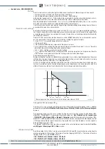
FUNCTION CHARACTERISTICS
51LR-diagram.ai
t
LR
>
inv
0
T
RESET
Start ILR>
Trip ILR>
TR
IP
PI
NG M
AT
RI
X
(LE
D+R
EL
AY
S)
ILR>TR-K
ILR>TR-L
ILR>ST-K
t
LR
>
inv
I
L1L
I
L2L
≥
1
≥
1
ON
≡
Enable ILR> element
&
I
L3L
ILR> Enable
I
L1L
≥
I
LR
>
inv
I
LR
>
inv
I
L2L
≥
I
LR
>
inv
I
LR
>
inv
I
L3L
≥
I
LR
>
inv
I
LR
>
inv
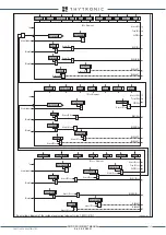
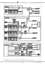
ILR> overcurrent element (51LR) block diagram
Block1, Block2
STOP
RUNNING
Mode51LR>
Binary input INx
T
0
Logic
INx
t
ON
INx
t
ON
INx
t
OFF
T
0
n.o.
n.c.
INx
t
OFF
Speed control
Speed control
“0”
Speed control
Mode51LR
“0”
“0”
without speed control
with speed control
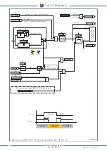
Locked rotor - First element logic diagram
XMR-D EQUIPMENT MANUAL
Ed. 2.9 - 02/2021


