202
FUNCTION CHARACTERISTICS
—
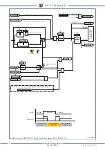
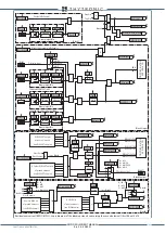
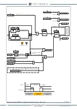
Voltage controlled/restraint overcurrent - 51V
Preface
The short circuit current of the generator can be detected even if the fault current drops below the
nominal current by means the voltage dependant overcurrent protection.
(case of generators with excitation derived from terminals or, in the case of excitation by a separate
supply, but with voltage regulator faults).
The protection may be employed as an alternative to the Underimpedance protective (21).
Current measurement may be performed with phase CT located on the generator star point side or
line side, but location on the star point side is to be preferred so that protection of the machinery is
achieved even with the machine breaker open; for the same reason the CB side of generator is the
VTs preferred position.
Two operation thresholds, that are modified dynamically on the grounds of the measured voltages
,independently adjustable (
I
-I/U
>,
I
-I/U
>>) with adjustable delay (
t
I-I/U>
,
t
I-I/U>>
).
Operation and settings
The following measures are involved:
• U
12
,
U
23
,
U
23
fundamental component of phase-to-phase voltages,
• I
L1L
,
I
L 2L
,
I
L 3L
fundamental component of line currents on sile L.
Both the thresholds have definite time characteristic.
The current-voltage trip characteristics of the protective device may be selected from two types:
• voltage controlled
, where the current threshold of the protective device is changed from an adju-
stable value corresponding to operation under load (
I
-I/U
>
def
for the first threshold,
I
-I/U
>>
def
for
the second threshold) to a lower value corresponding to short-circuiting (K∙
I
-I/U
>
def
for the first
threshold, K∙
I
-I/U
>>
def
for the second threshold with adjustable reduction factor K common to both
thresholds), when the voltage drops below an adjustable threshold (
U
-I/U
< common to both thre-
sholds). In addition, the corresponding trip times may be adjusted for each of the two thresholds.
The voltage-controlled feature is used when several generators are connected in parallel over the
same bar. Current above the associated pickup value is detected and a start is issued. After expiry
of the associated operate time (
t
I-I/U
>
def
,
t
I-I/U
>>
def
), a trip command is issued; if instead the cur-
rent drops below the threshold, the element is restored.
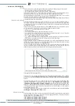
• voltage restraint
, where, for the first threshold, if the voltage exceeds the threshold
U
-I/U-1
< then
the adjustable current threshold
I
-I/U
>
def
is enabled, if the voltage is less than the threshold
U
-I/U-2
<
then the threshold K∙
I
-I/U
>
def
with adjustable reduction factor K is enabled, whilst if the voltage lies
between the thresholds
U
-I/U-1
< and
U
-I/U-2
< then the current threshold varies between the values
I
-I/U
>
def
and
I
-I/U
>
def
proportionally to the measured voltage. The same for the second threshold;
the current threshold
I
-I/U
>>
def
with the relevant reduction K∙
I
-I/U
>>
def
are adjustable. The voltage
threshold
U
-I/U-1
< and
U
-I/U-2
< and reduction factor K adjustments are common to both the thre-
sholds. Current above the associated pickup value is detected and a start is issued. After expiry of
the associated operate time (
t
I-I/U
>
def
,
t
I-I/U
>>
def
), a trip command is issued; if instead the current
drops below the threshold, the element is restored. The voltage restraint feature is used when the
t-int-F51V.ai
I
L
I
-I/U
>>
t
-I/U
>>
t
-I/U
>
I
-I/U
>
t
TRIP
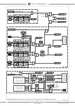
General operation time characteristic for the voltage controlled overcurrent elements - 51V
51V-VC_char.ai
Voltage
Voltage
Current threshold
Current threshold
U
-I/U
<
U
-I/U
<
I
-I/U
>
K
I
-I/U
>
I
-I/U
>>
K
I
-I/U
>>
Voltage restraint thresholds
XMR-D EQUIPMENT MANUAL
Ed. 2.9 - 02/2021


