FUNCTION CHARACTERISTICS
329
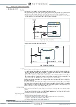
BF(H) start from Circuit breaker
By means CB(H) Input parameter it is possible enable the control of CB Side H status or CB Side L
status if BF(H) Start is active.
CB status control is enable by setting CB Side H in CB(H) Input parameter and if two binary inputs are
configured in order to acquire the status of CB Side H auxiliary contacts (52a and 52b).
CB Side H status enabling is available in
Set \ Profile A (or B) \ Breaker failure-BF(H)
menu, while
CB Side H acquisition function assignment to the logic inputs (52a Side H and 52b Side H) is settable
in
Set\Inputs ING1(X)\ Binary input IN1-1...(INX-y)
menus.
If CB(H) Input parameter is set as CB Side L, the same considerations given above are valid, but
carring out the control on CB Side L status, therefore two binary inputs are configured in order to
acquire the status of CB Side L auxiliary contacts (52a and 52b).
CB Side L acquisition function assignment to the logic inputs (52a Side L and 52b Side L) is settable
in
Set\Inputs ING1(X)\ Binary input IN1-1...(INX-y)
menus.
Relevant CB status must be enabled only if required by application.
To enable the BF(H) protection to operate with trips coming from external protections, one binary
input must be designed to acquire the relative contacts.; for this purpose it is necessary select
Trip-
ProtExt
Side H function in
Set\Inputs ING1(X)\ Binary input IN1-1...(INX-y)
menus.
All parameters I
BF(H)
>, I
EBF(H)
> and t
BF(H)
are settable separately for profile A and Profile B calibration
sets by
Set \ Profile A (or B) \ Breaker failure-BF Side H
menus.
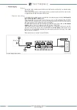
Logical block (Block1)
If
BF(H)-BLK1
parameter [BF(H) logical block] is set to
ON
, and a binary input is designed for logi-
cal block (Block1), BF(H) protection is blocked for the binary input activation time. Trip timer is held
in reset condition, so the operate time counting starts when the input block goes down.
[1]
Logical block enabling parameter is available in
Set \ Profile A (or B) \ Breaker failure-BF(H)
menu,
while the
Block1(H)
function must be assigned to the selected binary input in
et\Inputs ING1(X)\
Binary input IN1-1...(INX-y)
menus.
Note 1 The exhaustive treatment of the logic block (Block 1) function may be found in the “Logic Block” paragraph inside
CONTROL AND MONITORING
section
all-FBF(H).ai
Block1
B L K1 B F (H)
I
L1H,
I
L2H,
I
L3H
I
ECH
5 2 a / 5 2 b Side H
Tr ip P r o t E x t Side H
S t ar t B F (H)
Tr ip B F (H)
Block1
&
BF(H)-BLK1
BF(H) Enable
I
BF(H)
>
I
EBF(H)
>
t
BF(H)
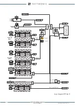
General logic diagram of the breaker failure element - BF (H)
5 2 a / 5 2 b Side L
CB(H) Input
XMR-D EQUIPMENT MANUAL
Ed. 2.9 - 02/2021


