MEASURES, LOGIC STATES AND COUNTERS
359
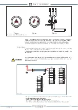
When a higher level anomaly is recognized
all protective functions are disabled
and the output relays
switch in no-trip state:
• rest state if the output relay are set in
De-energized
mode
(contacts as shown in the diagrams)
• active state if the output relay are set in
Energized
mode (opposite to what is shown in the dia-
grams).
The connections of the trip and diagnostic relays must be performed according to the application:
when the output relay must be normally energized and the circuit breaker must be open in case of
failure of the protection system, the self-test function must be enabled and assigned to the normally
energized relay selected for tripping.
The diagnostic alarms can be allocated to an output relay; for this purpose the
Self-test relay
pa-
rameter can be set inside the
Set \ Self-test Relay
submenu.
—
Pilot wire diagnostic
Detailed diagnostic information about the pilot wire are available.
(
Read \ Pilot wire diagnostic
).
• BLIN1 pilot wire breaking diagnostic state
ON/OFF
• Pilot wire BLIN1 shorted
ON/OFF
—
Selective Block - BLOCK2
The input and output state concerning the selective block are available (
Read \ Selective block-
BLOCK2
).
Block2 input
• Phase protections input selective block state
BLK2IN-Iph
ON/OFF
• Ground protections input selective block state
BLK2IN-IE ON/OFF
• tB-Iph/IE Elapsed state
tB timeout
ON/OFF
Block2 output
• Starting state of phase protections enabled
for external selective block on output
ST-Iph-BLK2
ON/OFF
• Starting state of ground protections enabled
for external selective block on output
ST-IE-BLK2
ON/OFF
• Phase protections output
selective block state
BLK2-OUT-Iph
ON/OFF
• Ground protections
output selective block state
BLK2-OUT-IE
ON/OFF
• Phase and ground protections
• output selective block state
BLK2-OUT-Iph/IE
ON/OFF
—
Fault recording - SFR
Recording is triggered by one or more causes (up to 8 simultaneous):
• Activation (OFF-ON transition) of any relay programmed for trip of protection or control element
• External trigger (binary input programmed as
Fault trigger
)
Twenty faults are recorded into a circular FIFO (First In, First Out) buffer.
[1][2]
—
Event recording - SER
Recording is triggered by one or more causes:
• Start and/or trip of any enabled protection or control element
• Binary input activation (OFF-ON or ON-OFF transition)
• Power-on or power-down (Auxiliary power supply)
• Setting change.
One thousand events are recorded into a circular FIFO (First In, First Out) buffer.
[2][3]
Following information are stored in every record:
• Event counter
[4]
• Date and time
• Event cause (binary input/element trip/setting change)
—
Oscillography - DFR
Upon programmable trigger, the fault records are recorded in COMTRADE format; the sampled mea-
sures (24 sample per cycle) are stored in a circular shift memory buffer.
The fault record are self-triggered; they are stored in sequential order up the allocated memory is
used up after which the oldest memory is overwritten.
An operating procedure example for the digital fault recording is illustrated inside the Thyvisor
section.
Following parameters are user-programmable:
• Pre-trigger and post-trigger time
• Selected sampled quantities.
• Analog channels (1...12) allocation.
Note 1 Fault 0 is the newest fault, while the Fault 19 is the oldest fault
Note 2 Data are stored in non volatile memory; they are held in spite of power down
Note 3 Event 0 is the newest event, while the Event 299 is the oldest event
Note 4 Counter is updated at any new record; it may be cleared by means Thyvisor
XMR-D EQUIPMENT MANUAL
Ed. 2.9 - 02/2021


