FUNCTION CHARACTERISTICS
81
—
Underimpedance - 21
Preface
Underimpedance protection is typically used to protect the generator against short-circuit between
phases outwith the differential protection area 87G and as a backup to the latter.
It is frequently used in place of voltage-dependent Overcurrent protection 51V when coordination
with distance measuring protective devices is required on the HV step-up transformer side.
In this way, the protection coordination of impedance protection generator with distance network
protections is simplified, given that both protections are adjusted in p.u. impedance.
The impedance protection, as well as overcurrent voltage restraint protection (51V), allows for the
trip even though the short circuit current of the generator was reduced to values near or below the
rated current (so with a traditional overcurrent protection, there would be shooting in the group
when operating at full load or with little overloads).
The transient (X
d
’) and subtransient reactance (X
d
”) has a significant impact on the magnitude of the
fault currents generated within the machine during an event such as a 3 phase short-circuit with the
time constant Td’ and Td”.
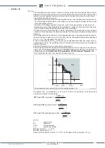
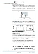
At the end of the transient the short-circuit current stabilizes at a value that depends primarily on:
• The type of excitation system. If powered by the generator terminal the permanent current vani-
shes because the terminals short circuit cancels the terminal voltages and the excitation system
can not therefore produce the field. For short-circuiting terminals most distant from terminals the
voltages does not vanish completely, but in any case the permanent short circuit current is less
than rated value. If the excitation is powered by a separate source or compound type (the short-cir-
cuit current providing energy required to sustain), the permanent current may be some multiple of
rated current (ie: 2 ... 4
I
n
)
• From the generator synchronous reactance Xd. Even with excitation system capable of forcing
the short circuit current, if the action of an automatic voltage regulator AVR is excluded (manual
adjustment), or the regulator itself is faulty, the permanent current is limited to the value correspon-
ding to the generator synchronous reactance (values near or below the rated current).
Typical values:
X
d
”=10...30%
T
d
”=20...50 ms
X
d
’=20...45%
T
d
’=0.5...3 s
X
d
=80...250%
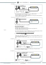
To ensure the generator protection even with the circuit breaker open, the phase CTs are placed on
the star center and the VTs are positioned between the generator terminals and the CB.
Operation and settings
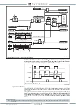
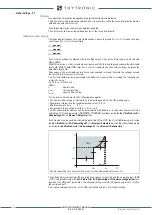
The impedance measurement is made for each phase on the basis of calculation:
Z
12
=
U
12
/
I
L1L
Z
23
=
U
23
/
I
L2L
Z
31
=
U
31
/
I
L3L
where
U
12
,
U
23
e
U
31
are the fundamental components of the phase-to-phase voltages and
I
L1L
,
I
L2L
I
L3L
are the fundamental components of the phase currents on side L.
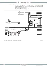
Two thresholds, independently adjustable with adjustable delay (.
The second threshold typically used to protect the generator and the first part of the MV transformer
windings, while the first threshold also the HV transformer winding; it must be properly delayed to
obtain time selectivity with distance protections.
A start is issued when at least one of the three impedances goes down the adjustable threshold;
after expiry of the associated operate time ( a trip command is issued; if instead the impedances
increases beyond the threshold, the element it is restored.
Icc-gen.ai
t
I
ng
2...4
I
ng
Symmetrical value of three-phase short
circuit current at the generator terminals
Separate excitation
or compound (AVR activated)
Separate excitation
or compound (AVR excluded)
Derived excitation
XMR-D EQUIPMENT MANUAL
Ed. 2.9 - 02/2021


