background image

7-5

ZR Owner’s Manual

OM0005_Rev A_ZR

CHAPTER 7: 

BACK UPHOLSTERY, SEAT UPHOLSTERY AND SEAT 

CUSHIONS


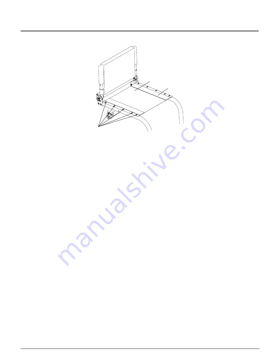
Allen 
Screws

Adjustment
Flap

Figure 7-7

Adjusting/Replacing

Bolt-On
Seat Sling

Replacing the Upholstery

Tools required:
• 

1/8” Allen Wrench

1.  Remove the seat cushion.
2.  Detach the back upholstery from the seat upholstery (see “Velcro

®

-Style Adjustable Back Upholstery” on page 7-1 

or “Tension Adjustable by Straps Back Upholstery” on pages 7-2 and 7-3).

3.  Remove all bolts that attach the seat upholstery to the chair frame.  See Figure 7-7.
4.  Remove the Bolt-On Seat Sling.
5.  If your replacement upholstery included new aluminum seat rails, proceed to Step 6.  If not, remove the aluminum 

seat rails from old upholstery and insert them into the new upholstery.

6.  Place the new seat upholstery on the frame and align the fastening holes in the upholstery and aluminum seat 

rails with the holes in the seat tubes of the frame.

7.  Loosely install all the bolts on the side of the seat sling where the adjustment lap is located.

8.  Install all the bolts on the opposite side of the seat sling and securely tighten.

9.  Detach the adjustment lap and adjust the seat upholstery to the desired tension.

10.  Fully tighten the bolts that attach the seat upholstery to the frame.
11.  Reattach the bottom of the back upholstery to the seat upholstery and replace the seat cushion.

Seat Cushions

Replacing the Foam Insert in the TiLite Seat Cushion

1.  Lift up and remove the existing seat cushion from the seat upholstery.
2.  Unzip the seat cushion cover and remove the foam insert.
3.  Insert the new foam insert into the seat cushion cover.
4.  Close the seat cushion cover and replace on the chair.

For seat cushions manufactured by manufacturers other than TiLite (

e.g.

 Corbee, StimuLite, Roho, Varilite), consult 

the owner’s manual provided by the applicable manufacturer.

Velcro

®

-Style Adjustable Seat Belt

I

WARNING

Installation of the Velcro

®

-Style Seat Belt must be performed by an authorized TiLite dealer or qualiied technician.

  If 

you ignore this Warning, serious injury may result.

Summary of Contents for ZR

Page 1: ...OWNER S MANUAL SERIAL NUMBER ______________________ ...

Page 2: ...ESCENDING A CURB OR SINGLE STEP 1 5 E DESCENDING A FLIGHT OF STAIRS 1 6 WARNINGS REGARDING FALLING AND TIPPING OVER 1 6 A CENTER OF GRAVITY STABILITY AND BALANCE 1 6 B TRANSFERRING IN AND OUT OF YOUR WHEELCHAIR 1 7 C DRESSING UNDRESSING IN YOUR CHAIR 1 8 D BENDING LEANING REACHING 1 8 E MOVING BACKWARD 1 9 F WHEELIES 1 9 G OBSTACLES 1 10 H CURBS STEPS 1 10 I HILLS SLOPES RAMPS 1 10 J STAIRS 1 11 K...

Page 3: ...STABLE HIGH MOUNT FOOTREST 3 4 Adjusting the Angle 3 4 Adjusting the Height Replacing 3 5 FLIP BACK FOOTREST 3 5 Adjusting the Angle 3 5 Adjusting the Height Replacing 3 6 BUCKLE ADJUSTABLE CALF STRAP 3 6 VELCRO ADJUSTABLE CALF STRAP VELCRO PADDED ADJUSTABLE CALF STRAP 3 6 CHAPTER 4 BACKRESTS AND PUSH HANDLES 4 1 FOLDING ADJUSTABLE HEIGHT ANGLE BACKREST Titanium or Aluminum 4 1 Folding the Backres...

Page 4: ...red Side Guards 6 3 ADJUSTABLE FENDERED SIDE GUARD Aluminum 6 4 Mounting 6 4 Adjusting 6 5 CHAPTER 7 BACK UPHOLSTERY SEAT UPHOLSTERY SEAT CUSHIONS 7 1 VELCRO STYLE ADJUSTABLE BACK UPHOLSTERY 7 1 Adjusting the Tension 7 1 Replacing 7 1 TENSION ADJUSTABLE BY STRAPS BACK UPHOLSTERY 7 2 Adjusting the Tension 7 2 Replacing 7 3 CORBAC ADJUSTABLE CONTOUR BACK SUPPORT 7 3 TENSION ADJUSTABLE BY STRAPS SEAT...

Page 5: ... Uni Lock from the Push to the Pull Position 10 4 Repositioning the Handle of the Uni Lock Wheel Lock 10 4 UNI LOCK WITH EXTENSION HANDLES 10 6 ALUMINUM SCISSOR LOCK 10 6 Adjusting 10 6 Replacing 10 6 CHAPTER 11 CASTERS AND FORKS 11 1 STANDARD FORKS 11 1 Replacing Casters 11 1 Replacing Forks 11 1 SLIPSTREAM SINGLE SIDED FORK 11 2 Replacing Casters 11 2 Replacing Forks 11 2 ADJUSTING THE FRONT SEA...

Page 6: ... 12 3 CHAPTER 13 ANTI TIPS 13 1 REAR ANTI TIPS 13 1 Adjusting 13 1 Mounting 13 1 USER FRIENDLY ANTI TIPS 13 2 Engaging 13 2 Disengaging 13 2 Adjusting 13 3 Removing 13 3 Mounting 13 3 FRONT ROLLER 13 4 Removing 13 4 CHAPTER 14 TRANSPORT BRACKET OPTION 14 1 GENERAL WARNINGS 14 1 INTRODUCTION 14 2 SECURING THE WHEELCHAIR TO THE VEHICLE 14 2 WARRANTY MODIFICATION 14 3 ...

Page 7: ......

Page 8: ...een a heavier and less responsive chair and therefore you may be used to using more force than is necessary to maneuver your TiLite chair If you ignore these Warnings you may fall tip over or lose control of the wheelchair and seriously injure yourself or others or damage the wheelchair C WEIGHT LIMITATION IWARNING TiLite wheelchairs have a weight limitation which applies to the combined weight of...

Page 9: ...se extra care if you must ride your chair on any such surface If you have any doubt about your ability to negotiate a particular surface ALWAYS ask for assistance 2 Titanium does not rust or corrode Aluminum does not rust but it will corrode However contact with water or excess moisture may still damage parts or components of your TiLite wheelchair that are made from other materials and could caus...

Page 10: ...st cases stowing it in the trunk is the safest alternative 6 NEVER use any chair that has been involved in a motor vehicle accident A wheelchair that has been involved in a motor vehicle accident may be damaged in ways that are not readily apparent and which could cause the chair to fail in use If you ignore these Warnings you may fall tip over or lose control of the wheelchair and seriously injur...

Page 11: ... are learning a new assistance technique ALWAYS have an experienced attendant help you before attempting it on your own If you ignore these Warnings you may fall tip over or lose control of the wheelchair and seriously injure yourself or others or damage the wheelchair L STANDING ON YOUR CHAIR IWARNING Your TiLite wheelchair has been designed for use as a wheelchair not as a step ladder NEVER stan...

Page 12: ...AYS position the chair and rider facing away from the stairs with one assistant at the rear facing away from the stairs and one at the front of the chair facing the rider 3 The assistant at the rear of the chair is in control of this procedure He or she must tilt the chair back to its balance point on the rear wheels NEVER attempt to lift a wheelchair by lifting on any removable detachable parts i...

Page 13: ...n any removable detachable parts including upholstery and removable push handles or push handle grips 4 The second assistant at the front must stand at the third step from the top and irmly grasp a non detachable part of the front frame but NOT swing away hangers with both hands The second assistant must lower the chair one stair at a time by letting the rear wheels roll over the stair edge Each a...

Page 14: ... increase the likelihood of tipping over forward 2 Riding your chair on a ramp or slope On an up slope your weight shifts to the rear and a backward tip over becomes more likely On a down slope your weight shifts to the front of the chair and a forward tip over becomes more likely 3 The use of a backpack or other options and the amount of weight added by those options For example carrying a lot of...

Page 15: ...this may cause the chair to tip over and or roll away 11 When transferring into your chair ALWAYS transfer as far back onto your seat as possible in order to reduce the risk that the chair will tip over or move away from you causing you to fall 12 If possible ALWAYS try to avoid falling into your chair uncontrollably when transferring into your chair This places undue stress on your chair s compon...

Page 16: ...eaning ALWAYS grasp one rear wheel with one hand This will help to prevent a fall if the chair starts to tip over 12 ALWAYS rotate the casters until they are trailing forward This will make the chair more stable NOTE To get your casters to trail forward irst move your chair forward past the object you want to reach and second back up alongside the object By moving backward your casters will rotate...

Page 17: ...t to go up or down a single curb or step without an assistant UNLESS a you are a very skilled rider of your chair and b you have previously learned to safely do a wheelie in your chair and c you are sure you have the strength and balance to control your chair during any such maneuver 2 ALWAYS unlock and rotate anti tips up and out of the way so they do not prevent you from executing this maneuver ...

Page 18: ...alert for wet or slippery conditions or surfaces any changes in the grade of the slope such as a lip bump or depression and any drop off or lip at the bottom of a slope For example even a 3 4 inch lip at the bottom of a ramp can cause the casters to stop and cause the chair to tip forward 12 Ramps at your home and work must meet all legal requirements for your area including building codes If you ...

Page 19: ...ce in the down position unless a You have an attendant but your attendant must rotate the anti tips into the down position whenever he or she leaves you unattended in your chair even for a moment or b You have to climb or descend a curb or step or overcome an obstacle Even if this is the case only unlock the anti tips if you can safely climb or descend the curb or step or overcome the obstacle and...

Page 20: ...of your chair that affect its center of balance if you add a seating system to your TiLite chair ALWAYS use anti tips until you have fully learned to control your chair in its new coniguration 3 Keep in mind that adding a seating system also may inhibit the proper operation of a folding back wheelchair If you ignore these Warnings you may fall tip over or lose control of the wheelchair and serious...

Page 21: ... and tip forward 2 NEVER lift your wheelchair by grasping the footrests or the swing away hangers Footrests and swing away hangers are detachable and are not designed to support the weight of your chair If you do the footrests or the swing away hangers may detach causing you to drop the chair or you may break the footrests or the swing away hangers or cause them to become loose and break at a late...

Page 22: ...lation will extend the life of your tires and will reduce the rolling resistance of your chair making it easier to use 1 Check your tires WEEKLY for proper inlation The correct inlation level is imprinted on the tire sidewall 2 DO NOT use your chair if any of the pneumatic tires are under inlated or over inlated 3 If any tire is under inlated the chair may tend to veer to one side which could caus...

Page 23: ...vide secure points for an attendant or assistant to hold the rear of the chair to prevent a fall or tip over If you have an attendant or assistant you should have push handles installed on your chair by TiLite TiLite offers push handles that are integral to the back canes and bolt on push handles TiLite recommends that you do NOT use non TiLite bolt on push handles because they will damage the bac...

Page 24: ... to your TiLite chair and your chair does not have a power adaptable frame you may damage your chair and you will void your warranty In addition power drive systems are heavy and will affect the center of balance of your chair Any change to the center of balance of your chair could cause you to lose control or fall or tip over If you ignore these Warnings you may fall tip over or lose control of t...

Page 25: ...chart 2 If your inspection uncovers any problem make sure to service or repair the problem BEFORE using the wheelchair 3 If your inspection reveals any loose worn bent or damaged parts you MUST tighten repair or replace them before using your TiLite wheelchair 4 Clean your wheelchair ONLY in accordance with the instructions under Cleaning on page 2 3 5 Annually or more often if necessary you MUST ...

Page 26: ...y Inspect for rips or sagging Inspect fastening laps to ensure they are securely attached Inspect while seated to ensure sling supports your weight and does not touch crosstubes Casters Forks Inspect wheels and tires for cracks and wear Inspect wheel fork assembly for proper tension by spinning caster caster should come to a gradual stop if caster wobbles tighten the axle Inspect wheel fork assemb...

Page 27: ...Do NOT use Scotch Brite pads steel wool abrasive cleaners or petroleum derived products to clean a painted aluminum or titanium frame Cleaning the Upholstery 1 Regularly hand wash the seat sling and back upholstery using water and a mild detergent Always allow the upholstery to air dry before riding in the chair 2 NEVER machine wash the upholstery and NEVER machine dry the upholstery 3 When washin...

Page 28: ...vice Please note if more than one solution in the chart below applies to your particular adjustment issue always try one solution at a time until the problem is solved Chair Veers Right or Left Caster Flutter Looseness in Chair Squeaks and Rattles Sluggish Turning or Performance Floating Caster Solution If you have pneumatic front and or rear tires make sure that the tires are properly and equally...

Page 29: ...east 2 of ground clearance to permit you to maneuver over objects If you ignore this Warning you could fall tip over or lose control of the wheelchair and seriously injure yourself or others or damage the wheelchair Safe Tread If you ordered your wheelchair with either the Titanium Footrest with Flat ABS Cover ABS Cover with 2 Sides or the Titanium Open Loop Footrest enclosed with your chair are t...

Page 30: ...ound clearance and tighten the Allen screw in the left clamp so the left side of the footrest cannot change Note When adjusting the height of the footrest make sure that at least 1 3 4 of the extension tube remains up inside the frame tube See Figure 3 4 4 Repeat the procedure from Step 3 above on the right side of the footrest 5 When both sides are set at an equal distance from the loor make sure...

Page 31: ... to the desired height not less than 2 of ground clearance and tighten the Allen screw in the left clamp so the left side of the footrest cannot change 6 Repeat the procedure from Step 5 above on the right side of the footrest 7 When both sides are set at an equal distance from the loor make sure all four wheels are in contact with the loor and make sure that the Allen screw in each clamp is in th...

Page 32: ...High Mount Footrest Adjusting the Angle Tools needed 5 32 Allen Wrench no extension tubes 3 16 Allen Wrench extension tubes only 1 Loosen but do not remove the Allen screws See Figure 3 8 If your footrest has extension tubes see Figure 3 9 you will have 3 16 Allen screws in place of locknuts and you will only need to loosen these latter Allen screws to adjust the angle 2 Adjust the footrest to the...

Page 33: ...urposes of transferring into and out of the wheelchair See Figure 3 10 You can adjust the height of or replace the Flip Back Footrest by using the tools and following the procedures for adjusting the height of or replacing a footrest as set forth under Titanium Footrest with Flat ABS Cover on pages 3 1 and 3 2 Figure 3 10 Flip Back Footrest Adjusting the Angle Tools needed 3 16 Allen Wrench 1 Loos...

Page 34: ...r Titanium Footrest with Flat ABS Cover on pages 3 1 and 3 2 Buckle Adjustable Calf Strap Buckle Adjustable Calf Strap is shown in Figure 3 12 Install the calf strap as shown in Figure 3 12 Figure 3 12 Buckle Adjustable Calf Strap Velcro Adjustable Calf Strap Velcro Padded Adjustable Calf Strap The Adjustable Calf Strap and Padded Adjustable Calf Straps are shown in Figure 3 13 Install the calf st...

Page 35: ... the TiShaft Release Bar and pull up See Figure 4 1 2 Push the backrest forward toward the front of the chair Note If you have a Lock Down Backrest make sure the backrest is locked securely in the folded position Unfolding the Backrest 1 Lift up on the backrest and pull towards the rear of the chair 2 Make sure the backrest locks securely into place Unfolding the Lock Down Backrest 1 Push up the T...

Page 36: ...o securely attach the link to the backrest assembly 5 Repeat Step 4 on the other side of the chair 6 Securely tighten the Button Head cap screws stop bolts and nylock nuts Figure 4 3 Changing the Backrest Angle Nylock Nut Backrest Back Mount Backrest Cam Lock Washer Button Head Cap Screw Stop Bolt Adjusting the Backrest Height Tools Needed 5 32 Allen Wrench Note In order to adjust the backrest hei...

Page 37: ...s Allen Screws Backrest Note If your backrest is set to 8 and you need to adjust the backrest height to 9 to 11 the following procedure applies 1 Remove the backrest upholstery See Velcro Style Adjustable Back Upholstery or Tension Adjustable by Straps Back Upholstery on pages 7 1 to 7 3 2 Remove the top end caps See Figure 4 5 3 Install the backrest sleeve in each backrest tube 4 Align the backre...

Page 38: ...dles should only be used on aluminum backrests Mounting Tools Needed 3 16 Allen Wrench 5 32 Allen Wrench 1 See Figure 4 7 for the correct location to mount the Bolt On Push Handles to the rigidizer bar 2 Assemble the two halves of the clamp around the rigidizer bar See Figure 4 8 3 Using the 3 16 Allen wrench insert the 1 Allen screw through a washer into the bottom hole on the clamp and loosely t...

Page 39: ...ighten 4 Insert the push handle through the clamp until the handle is at the desired height and securely tighten the quick release cam lock Note The quick release cam lock enables the user to easily disengage and engage the clamp for purposes of repositioning or removing the push handles IWARNING Your assistant or attendant should NEVER attempt to lift a wheelchair up a curb step or light of stair...

Page 40: ...DLES Top View Figure 4 9 Adjustable Height Push Handles Figure 4 10 Adjustable Height Push Handles Allen Screws Quick Release Cam Lock Clamp Push Handle Removing Tools Needed 3 16 Allen Wrench 1 Remove the four Allen screws See Figure 4 10 2 Remove the clamp and cam lock ...

Page 41: ...e the receiver thoroughly If this does not solve the problem check the nylon sleeves for wear Figure 5 1 Operating the Swing Away Armrest Armrest Armrest Stop Notch Receiver Adjusting the Angle Tools Needed 7 16 Open End Wrench 5 32 Allen Wrench 1 Remove the armrest from the receiver 2 On one side of the chair loosen but do not remove the nylock nuts while holding the locking block in position wit...

Page 42: ...d fall tip over or lose control of the wheelchair and seriously injure yourself or others or damage the wheelchair Note Never lift your chair using the desk arm mount See Figure 5 5 Adjusting the Armrest Height 1 Pull up on the height adjustment lever to permit the armrest to be raised or lowered to the desired height See Figure 5 4 2 After repositioning the armrest to the desired height release t...

Page 43: ...mrest raise the front of the armrest and rotate it straight back as far as possible Reverse this procedure to return the armrest to its original position See Figure 5 6 To swing away the armrest lightly lift up on the armrest and rotate the armrest away from the chair See Figure 5 6 To replace the armrest swing it back towards the chair and gently push it back down into place Note The Swing Away A...

Page 44: ...d 5 32 Allen Wrench 1 To adjust the angle at which the armrest sits when in the down position loosen but do not remove the Allen screw that secures the stop clamp See Figure 5 8 2 Slide the stop clamp forward on the armrest to lower the angle at which the armrest sits in the down position or slide the stop clamp rearward on the armrest to raise the angle 3 Securely tighten the Allen screw to ix th...

Page 45: ... canes and under the back upholstery lap 4 Replace the seat cushion Cloth Side Guard Figure 6 1 Removing Replacing Back Upholstry Flap Back Cane Fastening Flaps Rigid Removable and Quad Removable Side Guards Aluminum and Carbon Fiber Using Rigid Side Guards To remove either type of Rigid Side Guard lift the side guard out of the side guard mount by grasping it at the top or place inger in the hole...

Page 46: ...Tools Needed 3 16 Allen Wrench To remove the entire side guard assembly including the clamp 1 Remove the side guard from the side guard mount 2 Remove the Allen screw that secures the two halves of the clamp to the frame See Figure 6 3 Reinstalling Tools Needed 3 16 Allen Wrench 1 Align the two halves of the clamp around the seat tube of the chair frame See Figure 6 3 Note The half of the clamp to...

Page 47: ...Tools Needed 3 16 Allen Wrench 1 Align the two halves of the side guard clamp around the seat tube of the frame See Figure 6 4 Note The half of the side guard clamp to which the side guard mount is attached has a dowel pin protruding from the clamp that must be inserted in the side guard clamp hole in the frame 2 Insert the two Allen screws through the washers and the two halves of the clamp and s...

Page 48: ...s needed and allowing the Allen screws to slide within the cam slots 5 Once the desired side guard position has been achieved tighten the eight Button Head Cap screws four on each cam using the 5 64 Allen wrench 6 Using the 5 32 Allen wrench securely tighten Allen Screw 1 7 Keeping Allen Screw 2 in place using the 5 32 Allen wrench securely tighten the nylock nut using the 7 16 Open End wrench IWA...

Page 49: ...d position has been achieved tighten the eight Button Head Cap screws four on each cam using the 5 64 Allen wrench 6 Using the 5 32 Allen wrench securely tighten Allen Screw 1 7 Keeping Allen Screw 2 in place using the 5 32 Allen wrench securely tighten the nylock nut using the 7 16 Open End wrench IWARNING The threads on the Button Head Cap screws and Allen Screw 1 that secure the cams to the cam...

Page 50: ......

Page 51: ...ired adjust the tension of the strap s 6 Securely attach the padded back to the backrest ears using the Velcro style material and lower the back lap back into position in front of the rigidizer bar Figure 7 1 Adjusting Rigidizer Bar Padded Back Backrest Ears Back Flap Backrest Strap Replacing 1 Lift the back lap to expose the backrest ears See Figure 7 2 2 Completely detach the two backrest ears a...

Page 52: ...etach the padded back from the backrest ears Do not remove the backrest ears from the backrest 3 Adjust to the desired tautness by loosening the ear straps and then pulling on the loose end to pull the backrest ears closer together Tighter back upholstery will increase the stability and maintain normal maneuverability of the chair because the user is pushed forward slightly Looser back upholstery ...

Page 53: ...ecurely attach the padded back to the backrest ears and lower the back lap back into position in front of the rigidizer bar 11 Replace the seat cushion Figure 7 5 Replacing Padded Back Back Flap Backrest Bottom Flap Ear Straps Backrest Ears Corbac Adjustable Contour Back Support For information regarding the use and adjustment of the Corbac Adjustable Contour Back Support consult the owner s manua...

Page 54: ...olstery 8 Adjust the seat sling to the desired tension and fasten the tension adjustable straps 9 Place the chair onto all four wheels 10 Reattach the back upholstery to the seat upholstery Bolt On Seat Sling IWARNING Do not make the tension of the seat sling upholstery so loose that it does not properly support your weight You must never permit the sling to become so loose that your weight is bor...

Page 55: ...install all the bolts on the side of the seat sling where the adjustment lap is located 8 Install all the bolts on the opposite side of the seat sling and securely tighten 9 Detach the adjustment lap and adjust the seat upholstery to the desired tension 10 Fully tighten the bolts that attach the seat upholstery to the frame 11 Reattach the bottom of the back upholstery to the seat upholstery and r...

Page 56: ...n occurs discontinue use and consult your physician or seating specialist Failure to do so may result in serious injury such as pressure ulcers If you ignore any of these Warnings you may incur serious or life threatening injuries Installation The seat belt will be installed as shown in Figures 7 8 and 7 9 Figure 7 8 Velcro Style Seat Belt with D Ring Figure 7 9 Proper Belt Position for Belt with ...

Page 57: ...are the casters to the loor If you ignore this Warning your chair may not perform properly which in turn may cause you to fall tip over or lose control of the chair and seriously injure yourself or others or damage the chair Note It is recommended that you remove the rear wheels and turn the chair upside down before attempting to make any adjustments described in this chapter Standard Camber Mount...

Page 58: ...dicular to the ground and that the camber is oriented properly 7 Securely tighten both Allen screws 8 Reinstall the bumper assembly 9 Reinstall the rear wheels 10 Check the toe in toe out and adjust as needed See pages 8 2 and 8 3 Figure 8 2 Replacing the Camber Tube Camber Clamp Camber Tube Flats Allen Screw Bumper Assembly Adjusting Toe In Toe Out Tools Needed 3 16 Allen Wrench 7 8 Open End Wren...

Page 59: ...ear reference marks made in Step 6 See Figure 8 5 9 Measure the distance between the left and right tires at the front reference marks made in Step 7 10 If the measurements in Steps 8 and 9 are the same within 1 8 no toeing adjustment is needed and you may skip to Step 13 If not proceed to Step 11 11 Loosen the Allen screw in each camber clamp that secures the camber tube in place 12 If the measur...

Page 60: ......

Page 61: ...te end of the axle using the smaller wrench at the lats at the end of the axle 5 Depress the release button on the Quick Release Axle and slide the axle through the rear wheel hub 6 Depress the release button and reinstall the rear wheel into the axle sleeve or Zero Play camber tube 7 Before riding in the chair make sure the locking balls have fully secured the wheel in the axle sleeve or Zero Pla...

Page 62: ...n the chair make sure the locking balls have fully secured the wheel in the axle sleeve by pulling on the hub with the release handle in the locked position If the locking balls do not fully engage repeat these procedures to increase the play i e increase the distance between the quick release nut and the locking balls to permit the locking balls to fully engage properly Also check to make sure th...

Page 63: ...he chair and the quad quick release handle in the locked position so the locking balls are fully engaged be sure the collar is snug against the outer rear wheel bearing and securely tighten Set Screw 1 so the collar is securely on the axle 6 With the release handle in the unlocked position turn Set Screw 3 clockwise to remove any remaining play between the wheel hub and collar 7 Flip the quad quic...

Page 64: ......

Page 65: ...oving If not readjust the wheel locks until the wheel locks securely prevent the chair from rolling If you ignore this Warning you may fall tip over or lose control of the wheelchair and seriously injure yourself or others or damage the wheelchair Compact Push to Lock Adjusting Tools Needed 3 16 Allen Wrench 1 Loosen but do not remove the Allen screws in the wheel lock clamp See Figure 10 1 2 Adju...

Page 66: ...eel lock out of the clamp 3 Slide the new wheel lock into the wheel lock clamp but do not tighten the Allen screws 4 Follow the procedures under Compact Pull to Lock Adjusting on page 10 2 to position and secure the new wheel lock Compact Push to Lock and Compact Pull to Lock Wheel Locks with Extension Handles All of the adjustments set forth under Compact Push to Lock and Compact Pull to Lock on ...

Page 67: ... do not tighten the Allen screws 4 Follow the procedures under Compact Scissor Lock Adjusting on page 10 2 to position and secure the new wheel lock Uni Lock Adjusting Tools Needed 3 16 Allen Wrench 1 Loosen but do not remove the two Allen screws in the wheel lock clamp See Figure 10 4 2 Adjust the position of the wheel lock clamp on the frame so the wheel stop embeds at least 3 16 into the tire w...

Page 68: ... Uni Lock is set to the Push to Lock position Figure 10 6 Push to Lock Position Figure 10 5 Pull to Lock Position Socket Head Cap Screw Socket Head Cap Screw You can change the operation from pull to push or vice versa as follows 1 Remove the Socket Head Cap screw and reposition it to either the Pull to Lock or Push to Lock position as desired See Figure 10 7 2 Securely tighten the Socket Head Cap...

Page 69: ...wn in Figure 10 12 the wheel lock handle attaches to the wheel lock handle base with two Allen screws There is only one hole in the wheel lock handle base through which to attach the upper Allen screw There are three holes in the wheel lock handle base through which to attach the lower Allen screw 2 Remove the lower Allen screw and locknut that secure the wheel lock handle to the wheel lock handle...

Page 70: ...l of the adjustments set forth under Uni Lock on pages 10 3 to 10 6 apply to the Uni Lock with Extension Handles Aluminum Scissor Lock Adjusting Tools Needed 3 16 Allen Wrench 1 Loosen the two Allen screws in the wheel lock clamp See Figure 10 13 2 Adjust the position of the wheel lock clamp on the frame so the wheel stop embeds at least 3 16 into the tire when engaged in the locked position 3 Sec...

Page 71: ...rk sides Use one screw driver to hold one screw in place and securely tighten the other screw with the second screw driver Note If your chair has 4 or 5 TiLite Performance casters make sure that Spacer 2 which is wider than Spacer 1 is positioned on the recessed side of the caster which should be oriented outwards when the casters are in the trailing position Caster Cap Fork Washer Nylock Nut Cast...

Page 72: ...e Sided Forks Replacing Casters on page 11 2 2 Remove the nylock nut and washer that secure the fork to the fork stem See Figure 11 2 3 Remove the old fork and install the replacement fork on the fork stem 4 Replace the nylock nut and washer and securely tighten 5 Reinstall the casters See Slipstream Single Sided Forks Replacing Casters on page 11 2 IWARNING The ZR fork stem is permanently install...

Page 73: ...snapping the E ring into place See Figure 11 3 6 Replace the caster See Slipstream Single Sided Forks Replacing Casters on page 11 2 7 Follow Steps 1 through 6 on the opposite fork IWARNING Always use identical axle holes on both sides of your chair If you ignore this Warning you may fall tip over or lose control of the wheelchair and seriously injure yourself or others or damage the wheelchair IW...

Page 74: ... may have existed within the chair assembly 6 Make sure your footrest is set to your desired seat to footrest measurement and using a ruler or measuring tape make sure the left and right sides of the footrest are the same distance from the level surface It is important to have both sides of the footrest level and the footrest clamp screw tightened before the camber tube mount assemblies are tighte...

Page 75: ...Phillips screwdriver Note If your chair has 4 or 5 TiLite Litespeed casters make sure that Spacer 2 which is wider than Spacer 1 is positioned on the recessed side of the caster which should be oriented outwards when the casters are in the trailing position Replacing Casters Slipstream Single Sided Forks To replace the casters use the tools and follow the instructions under Slipstream Single Sided...

Page 76: ...s from the fork pivot and push out the pivot axle See Figure 11 9 3 Separate the two halves of the Glide fork 4 Using the Open End wrench loosen and remove the locknut and washer from the fork stem Slide the fork pivot and caster cap off of the fork stem Slide the caster cap and replacement fork pivot onto the fork stem and holding the parts in place slide the washer onto the fork stem and tighten...

Page 77: ...e the release button 5 Pull irmly on the wheel without depressing the release button to make sure the wheel is locked securely in place Quad Quick Release Axle Removing 1 Unlock the lever on the Quad Quick Release Axle See Figure 12 2 2 Slide wheel and axle out of the axle sleeve Replacing IWARNING Make sure the locking balls fully secure the Quad Quick Release Axle inside the axle sleeve before o...

Page 78: ... by pressing down on the pin in the center of the valve stem If you have a Presta valve see Figure 12 4 remove the valve stem cap unscrew counter clockwise the knurled nut on the valve stem and release all of the air from the tube by pressing down on the pin in the center of the valve stem 3 Remove the tire and inner tube 4 Make sure the rim strip is properly in place 5 Install the new inner tube ...

Page 79: ...damage the wheelchair Tools needed 7 8 Open End Wrench 3 4 Open End Torque Wrench 1 Place the 7 8 Open End wrench onto the camber plug and use the 3 4 Open End Torque wrench to remove the axle sleeve See Figure 12 5 Note If you have only one washer and do not have a lock washer your rear wheel spacing package will include a lock washer Always use a lock washer 2 Add or delete the spacers you need ...

Page 80: ......

Page 81: ...ng you may fall tip over or lose control of the wheelchair and seriously injure yourself or others or damage the wheelchair Tools Needed 5 32 Allen Wrench 3 16 Allen Wrench 7 16 Open End Wrench 1 Remove the rear wheels and place the frame upside down on a level surface 2 Remove the camber tube See Replacing the Camber Tube on page 8 2 3 Thread the Allen screw through the right side camber clamp ri...

Page 82: ...il the anti tip receiver re engages in the anti tip mount in the down position shown in Figure 13 3 Figure 13 3 Engaging Anti Tip Mount Release Lever Receiver Disengaging To disengage the User Friendly Anti Tip grip the anti tip irmly pressing down on the release lever raise the anti tip until the anti tip receiver re engages in the anti tip mount in the up position shown in Figure 13 4 Figure 13 ...

Page 83: ...jure yourself or others or damage the wheelchair IWARNING Do not disassemble the anti tip mounting assembly See Figure 13 6 If you ignore this Warning you may fall tip over or lose control of the wheelchair and seriously injure yourself or others or damage the wheelchair Tools Needed 5 32 Allen Wrench 3 16 Allen Wrench 5 64 Allen Wrench 1 Remove the rear wheels and place the frame upside down on a...

Page 84: ...aded hole in each of the anti tip mounts If you ignore this Warning you may fall tip over or lose control of the wheelchair and seriously injure yourself or others or damage the wheelchair IWARNING Before sitting in the chair make sure that the anti tips are operating properly To do this place the unoccupied chair on a level surface engage the anti tips and tip the chair backward until the anti ti...

Page 85: ...e yourself or others or damage the wheelchair Figure 13 7 Front Roller Allen Screws Front Roller With an Angle Adjustable Footrest 1 Remove the Allen screws that secure the Front Roller to the roller plate See Figure 13 8 2 Remove the Allen screws that secure the footplate and the clamp to the roller plate 3 Reassemble the angle adjustable footplate as shown in Figure 3 6 Note If removing the Fron...

Page 86: ......

Page 87: ...at is involved in any such incident IWARNING You MUST use your wheelchair in strict accordance with all warnings and instructions contained in this Owner s Manual IWARNING Whenever possible other auxiliary wheelchair equipment should be either effectively secured to the wheelchair or removed from the wheelchair and secured in the vehicle during transport so that such equipment does not break free ...

Page 88: ...A STICKER YOU MUST ASSUME IT IS EQUIPPED WITH THE TRANSPORT BRACKET OPTION TiSport LLC 2701 West Court Street Pasco WA 99301 Advena Ltd 33 Bridge Street Hereford HR4 9DQ UK SN 11902420 Figure 14 1 Transport Bracket Label SECURING THE WHEELCHAIR TO THE VEHICLE IWARNING The two front transport brackets see Figure 14 2 should NEVER be removed or relocated to another position on the wheelchair frame T...

Page 89: ...kets see Figure 14 2 is identiied with the symbol shown in Figure 14 3 Figure 14 2 Transport Brackets Wheelchair Transport Brackets Front View Back View Wheelchair Transport Brackets Figure 14 3 1 Carefully inspect each of the four transport brackets to ensure that they are properly secured to the wheelchair 2 Carefully inspect each wheelchair tie down strap for damage or wear 3 Each of the four w...

Reviews: