background image

5

Turn it back on

Important safety instructions

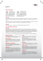
SAFETY

Overloading

Do not overload wall outlets or extension cords as this can result in the risk of fi re or 
electric shock. Overloaded AC outlets, extension cords, frayed power cables, damaged 
or cracked wire insulation, and broken plugs are dangerous. They may result in electric 
shock or fi re hazard. Periodically examine the power cable - if its appearance indicates 
damage or deteriorated receptacles have it replaced by your service technician.

Outdoor antenna grounding

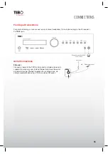
If an outside antenna or cable system is connected 
to the product, be sure the antenna or cable system 
is grounded so as to provide some protection against 
voltage surges and built-up static charges. The ex-
ample below is for reference only. Correct grounding 
should always be installed by an electrician.

Conditions requireing service

Unplug this product from the wall outlet and refer 
servicing to qualifi ed service personnel under the 
following conditions: 
A. If the unit exhibits sudden unusual operation or 

unusual display characteristics.

B.  If liquid has been spilled, or objects have fallen into the product.
C.  If the product has been exposed to rain or water.
D.  If the product does not operate normally by following the operation instructions, adjusting only those controls 

that are covered by the operation instructions. (NOTE: improper adjustment of other controls may result in 
damage and will often require extensive work by a qualifi ed technician to restore the product to its normal 
operation).

E.  If the product has been dropped or damaged in any way.
F.  

If the product exhibits a distinct change in performance.

Lightning

Unplug it from the wall outlet and disconnect the antenna or cable system. This will prevent damage to the prod-
uct due to lightning and power line surges.

Heat dispersion

Leave at least 10 cm of space between the top, back and sides of the unit 
and the wall or other components for proper ventilation.

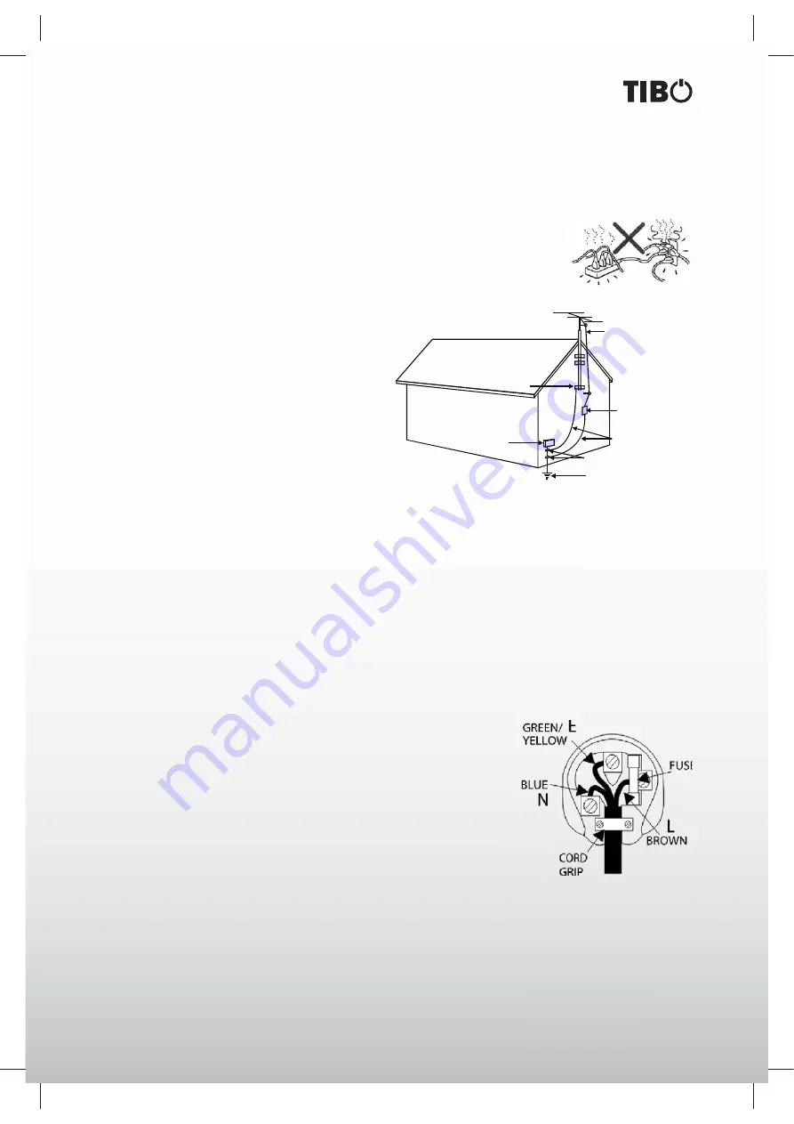
Plug fi tting instructions (UK only)
The cord supplied with this appliance is factory-fi ted with a UK mains plug 
fi ted with a 5-amp fuse inside. If it is necessary to change the fuse, it is im-
portant that a 5-amp fuse is used. If the plug needs to be changed because 
it is not suitable for your socket, or becomes damaged, it should be cut off 
and an appropriate plug fi ted following the wiring instructions below. The plug 
must then be disposed of safely, as insertion into a mains socket is likely to 
cause an electrical hazard. Should it be necessary to fi ta 3-pin BS mains 
plug to the power cord, the wires should be fi ted as shown in this diagram. 
The colours of the wires in the mains lead of this appliance may not correspond with the coloured markings 
identifying the terminals in your plug. Connect them as follows: The wire which is coloured BLUE must be con-
nected to the terminal which is marked with the letter ‘N’ or coloured BLACK. The wire which is coloured BROWN 
must be connected to the terminal which is marked with the letter ‘L’ or coloured RED. The wire which is coloured 
GREEN/YELLOW must be connected to the terminal which is marked with the letter ‘E’ or coloured GREEN.
If a standard 13-amp (BS 1363) plug is used, a 5-amp fuse must be fi ted or, if any other type of plug is used, a 
5-amp fuse must be fi ted, either in the plug or adaptor, or on the distribution board.

ANTENNA

LEAD  IN

WIRE

ANTENNA

DISCHARGE  UNIT

(NEC  SECTION  810-21)

GROUNDING  CONDUCTORS

(NEC  SECTION  810-21)

GROUND  CLAMPS

POWER  SERVICE  GROUNDING

ELECTRODE  SYSTEM

(NEC  ART  250.PART  H)

ELECTRIC

SERVICE

EQUIPMENT

GROUND

CLAMP

Summary of Contents for TI 1000 HC

Page 1: ...User Guide TI 1000 HC Turn it back on Please read this user manual carefully before using your TI 1000 HC and retain for future reference Optical 5 1CH Stereo System READY Coax in...

Page 2: ...6 616 6 487 535 7 212 872 7 333 929 7 392 195 7 272 567 other U S and worldwide patents issued pending DTS is a registered trademark and the DTS logos Symbol DTS HD and DTS HD Master Audio are tradema...

Page 3: ...ual After unpacking the unit please read the manual care fully and observe all the instructions given Power supply Only the power supply indicated on the rating plate must be used for this unit If you...

Page 4: ...ollowing cases A If the power cord or the plug is damaged B If liquid has been spilled on the unit or objects have fallen into the unit C If the unit has been exposed to liquid or moisture D If the un...

Page 5: ...outlet and disconnect the antenna or cable system This will prevent damage to the prod uct due to lightning and power line surges Heat dispersion Leave at least 10 cm of space between the top back and...

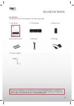
Page 6: ...epair is in it s original box packaging INCLUDED IN THE BOX Accessories Included with the TI1000 HC AV Receiver are the following accessories l o r t n o C e t o m e R x 1 l a u n a M r e s U x 1 1 x...

Page 7: ...different types of batteries together Rechargeable and non rechargeable batteries can be used Refer to the precautions on their labels When the remote control is not to be used for a long time more t...

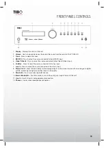
Page 8: ...BD DVD source equip ment for output through this unit 23 Video 1 Press to select the source connected to Video 1 for output 24 Delay Press this button to select the desired setting speaker then press...

Page 9: ...ngs Here only typical examples of speaker placement and recommendations are shown Important points regarding speaker placement Front Right and Left speakers and Center speaker Place these three speake...

Page 10: ...elect the source connected to the Aux input 7 Line In Press to select the source connected to the Line in input 8 Stereo Direct Press to listen directly to the analogue inputs for the current source w...

Page 11: ...when in tuner mode etc 5 Output channel indicators Shows the currently active channels depending on decoding mode and source material Channel icons lit indicate channels in the source material Icons...

Page 12: ...7 Component Inputs and Outputs Video1 and BD DVD 8 Digital Inputs S P DIF or Toslink digital inputs for each source You can choose to use a different type for each source but do not connect both at th...

Page 13: ...able from the side of the cable Connect this marked side to the red terminals and the unmarked side is the black terminal t Prepare the speaker cords for connection by stripping off approximately 10 m...

Page 14: ...nections can be made to this unit coaxial S P DIF and optical Toslink Either type can be used for a source as the TI1000 HC automatically uses the active one Note Only one connection type should be us...

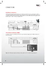
Page 15: ...VD Video 1 Video 2 CD Aux TV Tape MD CDR Video Output Connection HMDI Connection to the TV is by HDMI The TI1000 HC converts incoming analogue video to HDMI and scales it for best picture quality Note...

Page 16: ...AV receiver s PHONES jack Aerial Connections FM aerial Connect an aerial to the FM 75 ohm socket a simple wire aerial is supplied for temporary use Extend the lead and move the aerial around until you...

Page 17: ...d range 20 Hz to 20 kHz or greater In addition the surround channels were monaural the surround left and right channels were the same with previous Dolby Pro Logic but Dolby Pro Logic II they are play...

Page 18: ...is pressed momentarily step FM 50 kHz steps MW 9 kHz steps Two FM modes available Press STEREO or MONO button on remote control to select Stereo mode or Mono mode Stereo FM stereo broadcasts are recei...

Page 19: ...PLAY on remote control until the current time from Radio Station appears e g 15 30 Note 1 The Clock Time will be only transmitted from lo cal radio station once a minute so you need to wait for less t...

Page 20: ...ine in input on the front panel and place it at your normal listening position in the room Press the OSD button on the remote control to access the OSD and then select the Speaker Setup Menu Now selec...

Page 21: ...Speakers that exhibit very strong phase angles or deliberately wire some drive units out of phase can of course appear to the system as an out of phase speaker when correctly connected If a speaker i...

Page 22: ...ws to scroll through the options Now move down and by highlighting each speaker in turn and using the Left and Right arrows select from Large Small or None for each speaker Large or Small are used to...

Page 23: ...t value to that which you measured by using the Left and Right arrows the values do not need to be exact Press the OSD button to exit the menu Note In addition to the delays as set above Dolby Pro Log...

Page 24: ...o connection you want to use for that source Analogue Digital or HDMI input t The type of video connection you want to use for that source HDMI or CVBs YPbPr t The processing mode for that source TI 1...

Page 25: ...nactive as no bass has been re directed plus there is no LFE channel If it is desired to have the subwoofer running with all Large Speakers and these encoding types enable Bass Augment for PLII Neo 6...

Page 26: ...wn also as DTS HR an extension to the original DTS audio format DTS HD High Resolution Audio supports 5 1 fully discrete channels compared to DTS s 5 1 or 5 1 in its DTS ES Matrix or DTS ES Discrete v...

Page 27: ...are encoded into a Stereo mix by an analogue matrix process Dolby Pro Logic II material can be played back by normal Stereo equipment as Stereo or decoded into 5 channel surround sound Dolby Pro Logic...

Page 28: ...n is always applied for Dolby Digital and Dolby Digital Plus soundtracks The application and amount of compression to Dolby True HD sound tracks is dictated by the soundtrack itself Off No Compression...

Page 29: ...ine the frequency response of your system and where each speaker types bass response starts to tail off often called the 3dB or 6dB roll off cutoff point This would be approximately the point the corr...

Page 30: ...on the device that you want to make pairing place it near the system and set it into the pairing mode ll in 0000 4 Check to see that the Bluetooth module is detected by the Bluetooth wireless technol...

Page 31: ...mode to mono by pressing the STEREO MONO button Note that the broad cast will then be heard as mono sound Sound is distorted and or the volume level becomes low Broadcast signals are poor or poor ant...

Page 32: ...barrier free Features HDMI 1 4 1080P Support 3D TV and BD Audio Return TV Audio Through HDMI to TV Output 2 CH or Dolby 5 1CH after decoding Aluminum Panel VFD Display On Screen Display OSD Dual Core...

Page 33: ...3 Turn it back on CONTACTS Tibo Ltd DSV House Maidstone Road Milton Keynes MK10 0AJ United Kingdom tel 44 0 845 2711 906 e mail info tibo electronics com Proof of purchase attach your receipt here...

Page 34: ...Turn it back on www tibo electronics com...

Reviews: