
Synergy Controller Technical Manual, Revision H
Page 146
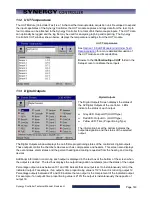
12.0 GRAPH SCREEN
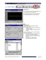
Graph Screen
Touch the screen to adjust the graph settings. Line
colors are defined in the screen below.
The settings for the Graph can be changed from
the Graph Settings folder in the Setup Screen.
12.1 Temperature / Humidity / Air Temperature
Graph Options
Select the individual checkboxes to display
specified graph lines.
♦
Temperature – displays the air temperature
inside the chamber.
♦
Humidity – displays the humidity inside the
chamber.
When the cascade control is enabled the graph
features map as follows:
♦
Temperature - displays the temperature of
the Unit-Under-Test in the chamber.
♦
Humidity - displays the humidity inside the
chamber.
♦
Air Temperature - displays the air
temperature inside the chamber
Summary of Contents for Synergy Compact
Page 14: ...Synergy Controller Technical Manual Revision H Page 14 2 0 SPECIFICATIONS 2 1 Data Sheet...
Page 71: ...Synergy Controller Technical Manual Revision H Page 71...
Page 106: ...Synergy Controller Technical Manual Revision H Page 106...
Page 123: ...Synergy Controller Technical Manual Revision H Page 123...
Page 141: ...Synergy Controller Technical Manual Revision H Page 141 TE1151 6 Triac Output Board Schematic...
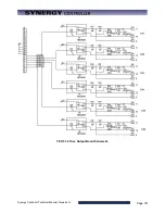
Page 142: ...Synergy Controller Technical Manual Revision H Page 142 TE1708 6 Relay Board Schematic...
Page 188: ...Synergy Controller Technical Manual Revision H Page 188...
Page 274: ...Synergy Controller Technical Manual Revision H Page 274 Synergy Controller Step Syntax...
Page 294: ...Synergy Controller Technical Manual Revision H Page 294...
Page 312: ...Synergy Controller Technical Manual Revision H Page 312...
Page 345: ...Synergy Controller Technical Manual Revision H Page 345...
Page 346: ...Synergy Controller Technical Manual Revision H Page 346...






![Lambrecht power[cube] 30.95800.015000 Manual preview](http://thumbs.mh-extra.com/thumbs/lambrecht/power-cube-30-95800-015000/power-cube-30-95800-015000_manual_3388101-01.webp)


