Synergy Controller Technical Manual, Revision H
Page 148
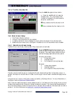
13.1.2 Turn the chamber On
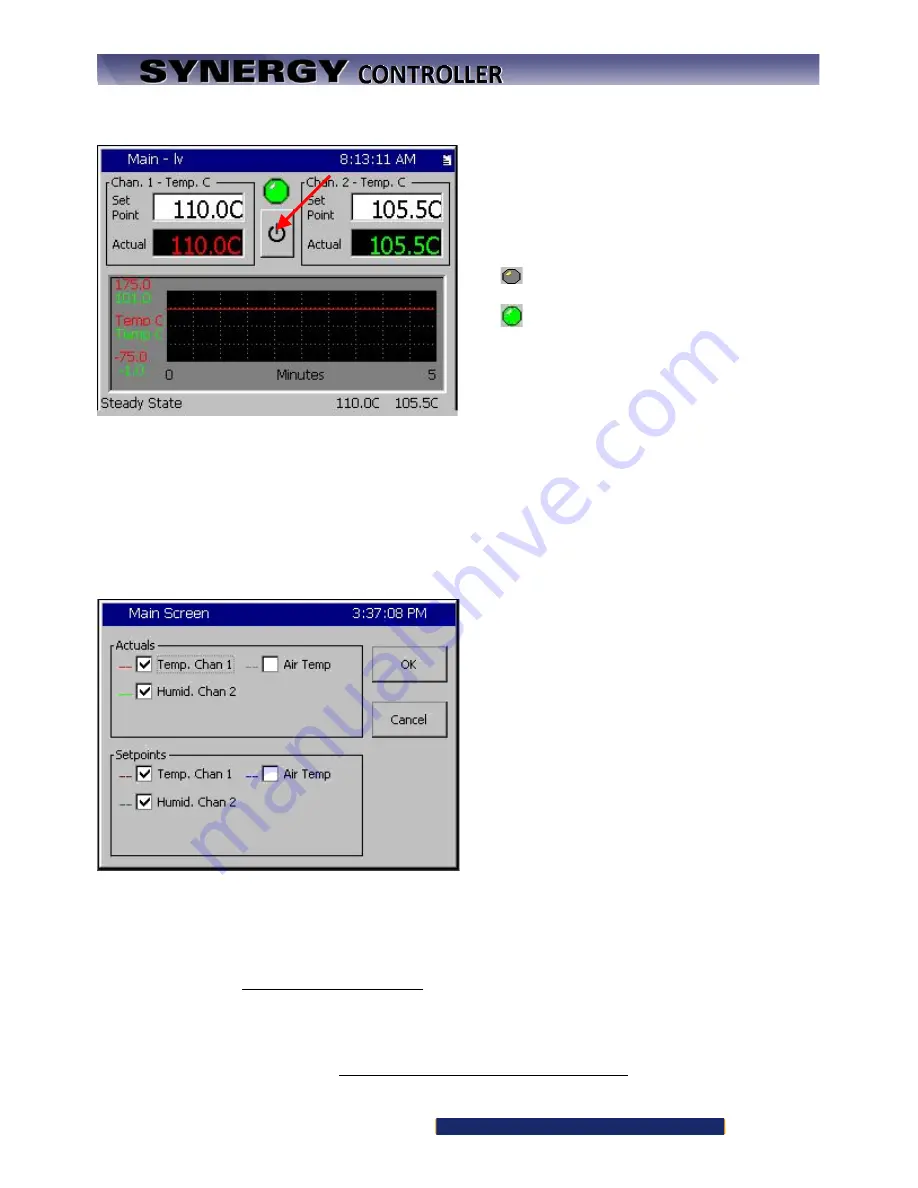
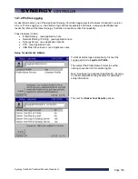
Press the
MAIN
Navigation Screen button.
♦
Press the
on/off
button to toggle the
chamber state. The current state of the
chamber is indicated by the LED indicator
above the on/off button.
Gray indicates that the chamber is Off.
Green indicates that the chamber is On
13.2 Main Screen Setup
•
The Process Graph is optional
•
The size of the channel text can be adjusted.
•
A chamber light button can be displayed to control an Event assigned to the chamber light.
•
Additional sensor values can be arranged on the Main screen to show additional test variables.
13.2.1 Main Screen Graph Setup
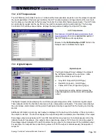
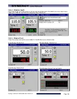
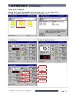
The Main Screen can display a small graph of the process and set point data.
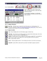
Press the
MAIN
Navigation Screen button. To
modify the data displayed on the graph press on
the graph. The graph settings window will open
with the following graph data selection options:
Actuals (process data)
♦
Temperature Actual
♦
Humidity Actual
♦
Air Temperature Actual (Cascade)
Setpoints
♦
Temperature Setpoint
♦
Humidity Setpoint
♦
Air Temperature Setpoint (Cascade)
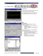
The time scale and vertical axes are configurable from the Graph Settings folder on the Setup screen. In
addition, the Graph can be switched off to allow room for larger channel values or additional Display Sensor
points.
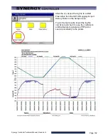
A larger full-screen version of the graph is always available on the Graph Screen. For more information on
the graph screen see
Note: Cascade enabled chambers provide additional options on the Main screen for viewing the two process
variables associated with the Cascade controlled temperature channel. The channel data toggles between
the product temperature and the air temperature for a cascade channel when the Actual (process) variable is
pressed. For more information see
Section 14.0 Cascade Temperature Control
Summary of Contents for Synergy Compact
Page 14: ...Synergy Controller Technical Manual Revision H Page 14 2 0 SPECIFICATIONS 2 1 Data Sheet...
Page 71: ...Synergy Controller Technical Manual Revision H Page 71...
Page 106: ...Synergy Controller Technical Manual Revision H Page 106...
Page 123: ...Synergy Controller Technical Manual Revision H Page 123...
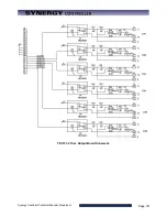
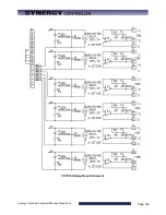
Page 141: ...Synergy Controller Technical Manual Revision H Page 141 TE1151 6 Triac Output Board Schematic...
Page 142: ...Synergy Controller Technical Manual Revision H Page 142 TE1708 6 Relay Board Schematic...
Page 188: ...Synergy Controller Technical Manual Revision H Page 188...
Page 274: ...Synergy Controller Technical Manual Revision H Page 274 Synergy Controller Step Syntax...
Page 294: ...Synergy Controller Technical Manual Revision H Page 294...
Page 312: ...Synergy Controller Technical Manual Revision H Page 312...
Page 345: ...Synergy Controller Technical Manual Revision H Page 345...
Page 346: ...Synergy Controller Technical Manual Revision H Page 346...





![Lambrecht power[cube] 30.95800.015000 Manual preview](http://thumbs.mh-extra.com/thumbs/lambrecht/power-cube-30-95800-015000/power-cube-30-95800-015000_manual_3388101-01.webp)


