Synergy Controller Technical Manual, Revision H
Page 20
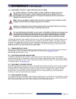
4.0 EQUIPMENT SAFETY AND CONTROLLER ALARMS
No complex software or hardware system is perfect. Defects are always present in a
software system of any size. In order to prevent danger to life or property, it is the
responsibility of the system designer to incorporate redundant protective mechanisms
appropriate to the risk involved.
Make sure you completely understand the operation and function of the chamber and the
Synergy Controller before you begin using your test chamber.
Dangerous voltages are present in this equipment. Disconnect electrical service of source
and tag circuit out before servicing or replacing components.
Do not use the Synergy Controller in any manner not specified in this manual. Improper use
may impair the safety features employed and may void your test chamber and controller
warranty. Failure to follow the proper operating procedures listed throughout any of the
information provided could cause damage to your equipment, personal injury or death.
The Synergy Controller offers multiple built-in alarms to protect the equipment (test chamber, process oven,
thermal platform etc.) and the unit-under-test from conditions outside their ratings. The alarms should be
carefully set to appropriate limits based on the capabilities of the equipment and the safe limits of product
exposure. In addition to these built-in alarms, a secondary controller should always be employed to offer
further protection in the case of sensor or controller failure.
4.1 Standard Alarm Limits
The Synergy Controller features standard high and low absolute limits and high and low deviations limits for
each channel. Look for the alarms in the setup folder for each channel in
SETUP/Calibration/Channel 1, 2, etc.
4.2 User Programmable Alarm Limits
In addition to the standard alarm limits, the Programmable User Alarm System can provide additional
protection against open or failed sensors and process variable outside expected limits. User alarms can be
created using redundant sensors for any channel and provide shut down protection to reduce the probability
of machinery failure. See
4.3 Secondary Controller Alarms
Redundant protective mechanisms such as a TempGard limit controller should be used to provide complete
protection against controller and/or sensor failure. When used with a separate sensor, secondary alarm
controllers reduce the probability that a single point failure will cause damage to the chamber or to the
product inside. The secondary controller should be wired to remove power from all of the chamber’s
machinery in order to provide maximum protection.
4.4 Alarm System Testing
It is important that users periodically verify all alarm systems by test. As a minimum, it is important to confirm
that chamber shut down occurs and power is removed from heaters, compressor, etc. when standard alarm
limits, user programmable alarm limits and secondary controller limits are reached.
Summary of Contents for Synergy Compact
Page 14: ...Synergy Controller Technical Manual Revision H Page 14 2 0 SPECIFICATIONS 2 1 Data Sheet...
Page 71: ...Synergy Controller Technical Manual Revision H Page 71...
Page 106: ...Synergy Controller Technical Manual Revision H Page 106...
Page 123: ...Synergy Controller Technical Manual Revision H Page 123...
Page 141: ...Synergy Controller Technical Manual Revision H Page 141 TE1151 6 Triac Output Board Schematic...
Page 142: ...Synergy Controller Technical Manual Revision H Page 142 TE1708 6 Relay Board Schematic...
Page 188: ...Synergy Controller Technical Manual Revision H Page 188...
Page 274: ...Synergy Controller Technical Manual Revision H Page 274 Synergy Controller Step Syntax...
Page 294: ...Synergy Controller Technical Manual Revision H Page 294...
Page 312: ...Synergy Controller Technical Manual Revision H Page 312...
Page 345: ...Synergy Controller Technical Manual Revision H Page 345...
Page 346: ...Synergy Controller Technical Manual Revision H Page 346...

