Synergy Controller Technical Manual, Revision H
Page 209
15.8 Alarm System Test
After installation and setup, all alarm should be tested to verify that test chamber shut down occurs and
power is removed from heaters, compressor, etc. when any sensor is disconnected. Verify that test
chamber shut down occurs when the secondary limit controller alarm limits are reached. (See the
15.9 Control System Verification
Verify control system performance for transient and steady state control. Tune the PID settings as
necessary. (See
) Consult the factory for additional assistance with chamber tuning.
15.10 Controller Splash Screen
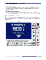
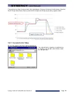
When power is applied to the chamber, the Synergy Controller touch-screen displays boot-up progress.
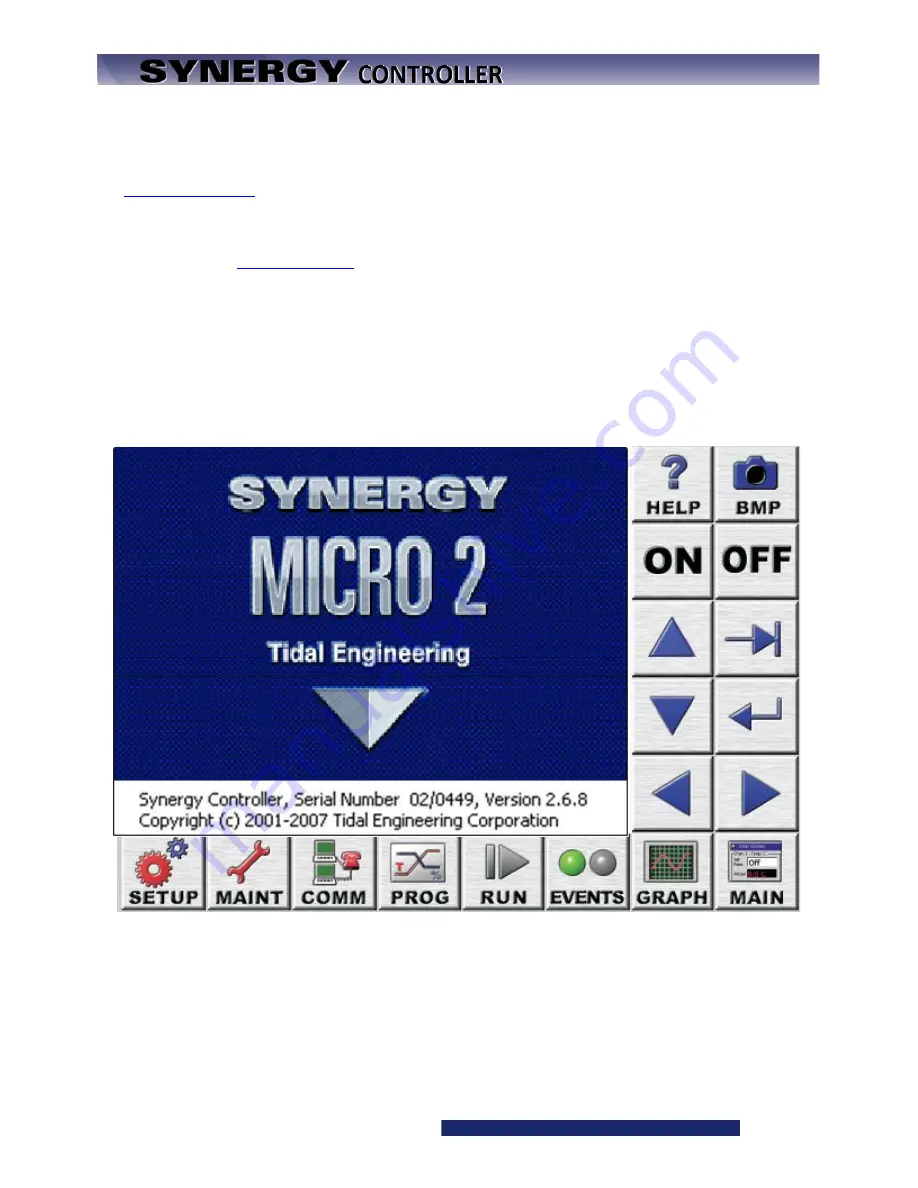
Upon a successful boot-up, a Synergy Controller splash screen will appear. (See figure below) followed by
the Main screen.
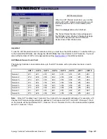
Synergy Controller Splash Screen
Summary of Contents for Synergy Compact
Page 14: ...Synergy Controller Technical Manual Revision H Page 14 2 0 SPECIFICATIONS 2 1 Data Sheet...
Page 71: ...Synergy Controller Technical Manual Revision H Page 71...
Page 106: ...Synergy Controller Technical Manual Revision H Page 106...
Page 123: ...Synergy Controller Technical Manual Revision H Page 123...
Page 141: ...Synergy Controller Technical Manual Revision H Page 141 TE1151 6 Triac Output Board Schematic...
Page 142: ...Synergy Controller Technical Manual Revision H Page 142 TE1708 6 Relay Board Schematic...
Page 188: ...Synergy Controller Technical Manual Revision H Page 188...
Page 274: ...Synergy Controller Technical Manual Revision H Page 274 Synergy Controller Step Syntax...
Page 294: ...Synergy Controller Technical Manual Revision H Page 294...
Page 312: ...Synergy Controller Technical Manual Revision H Page 312...
Page 345: ...Synergy Controller Technical Manual Revision H Page 345...
Page 346: ...Synergy Controller Technical Manual Revision H Page 346...

