Synergy Controller Technical Manual, Revision H
Page 39
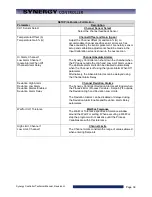
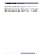
SETUP\Calibration\Calibration
Parameter
Description
CH1 Sensor Select
Channel Sensor Select
Select the channel feedback Sensor
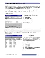
Temperature Offset (b)
Temperature Gain %(m)
Channel Offset and Gain (Span)
Adjust the Channel Offset (b) and Gain %(m) to
accommodate channel specific sensor errors such as
those caused by the sensor placement. Generally, sensor
setup and calibration adjustment should be made in the
Input Calibration screens shown in the next section.
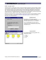
Hi Alarm, Channel 1
Low Alarm Channel 1
Ignore Alarm When Off
Channel Alarm Delay
Channel Absolute Alarms
The Synergy Controller can shut down the chamber when
the PV goes outside the High and Low Limit Alarm values.
The absolute alarm limits can be disabled automatically
when the Channel is off using the Ignore Alarm When Off
parameter.
Alternatively, the Absolute Alarms can be delayed using
the Channel Alarm Delay.
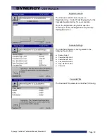
Deviation High Alarm
Deviation Low Alarm
Deviation Alarms Enabled
Deviation Alarm Delay
Channel Deviation Alarms
The Synergy Controller Deviation Alarms will trigger when
the Process Error (Process Variable – Setpoint) is outside
the Deviation High and Deviation Low Limits.
The Deviation Alarms can be disabled or delayed using
the Deviation Alarm Enable and Deviation Alarm Delay
parameters.
Waitfor CH1 Tolerance
Wait For Tolerance
The Wait For Tolerance specifies a tolerance window
around the Wait For setting. When executing a Wait For
step the program will not advance until the Process
Variables are within this tolerance.
High Limit, Channel 1
Low Limit, Channel 1
Channel Limits
The Channel Limits constrain the range of values allowed
when entering Setpoints.
Summary of Contents for Synergy Compact
Page 14: ...Synergy Controller Technical Manual Revision H Page 14 2 0 SPECIFICATIONS 2 1 Data Sheet...
Page 71: ...Synergy Controller Technical Manual Revision H Page 71...
Page 106: ...Synergy Controller Technical Manual Revision H Page 106...
Page 123: ...Synergy Controller Technical Manual Revision H Page 123...
Page 141: ...Synergy Controller Technical Manual Revision H Page 141 TE1151 6 Triac Output Board Schematic...
Page 142: ...Synergy Controller Technical Manual Revision H Page 142 TE1708 6 Relay Board Schematic...
Page 188: ...Synergy Controller Technical Manual Revision H Page 188...
Page 274: ...Synergy Controller Technical Manual Revision H Page 274 Synergy Controller Step Syntax...
Page 294: ...Synergy Controller Technical Manual Revision H Page 294...
Page 312: ...Synergy Controller Technical Manual Revision H Page 312...
Page 345: ...Synergy Controller Technical Manual Revision H Page 345...
Page 346: ...Synergy Controller Technical Manual Revision H Page 346...

