Synergy Controller Technical Manual, Revision H
Page 173
15.0 INSTALLATION AND TROUBLESHOOTING
The Synergy Controller is designed for both new equipment and retrofit applications. This section provides
an overview of the controller installation process.
Note that some of these steps are simplified for VersaTenn, VersaTenn II and VersaTenn III retrofits since
those systems will already have the output boards installed. These steps are noted as such.
The Synergy Controller is engineered as a drop-in replacement for Tenney VersaTenn III controllers,
employing virtually identical electrical, mechanical, and physical interfaces. Available with either a front or
flush mounted 320 x 240 (color STN) touch screen, the multi-channel Synergy Controller makes the retrofit
process fast and easy.
Detailed chamber specific retrofit installation instructions are available for some chambers at
Dangerous voltages are present in this equipment. Disconnect electrical service of source
and tag circuit out before servicing or replacing components.
15.1 Installation Check List
The Synergy Controller installation consists of the six steps summarized here:
1. Configuration selection; Select the appropriate configuration for your test chamber, i.e.
Temperature/Humidity, Temperature/Pressure, etc.
2. Mount the controller and the other components.
3. Wire the controller, output boards, etc.
4. Setup the controller.
5. Test alarm systems.
6. Verify control system performance for transient and steady state testing.
15.2 Chamber Configuration Selection
To begin the installation process, select the configuration appropriate for your test chamber, i.e.
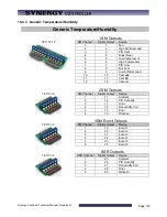
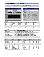
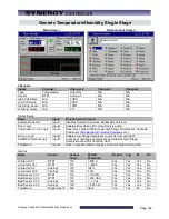
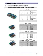
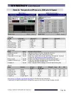
Temperature/Humidity, Temperature/Pressure, etc. See Section 15.4 for a list of standard configurations.
Consult the factory for custom configurations.
15.3 Controller Setup
Once the Synergy Controller and output boards are mounted and wired check the tightness of all
connections. Then apply power to the system and configure the controller. To configure the controller:
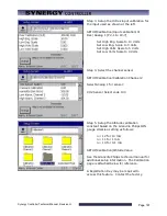
1. Startup the controller and select the chamber type from the Setup/Chamber setup folder.
2. Check the Input calibration for all inputs and the sensor selection for each channel. Change as
necessary.
3. Setup the channel alarms and any other alarms (see the
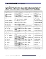
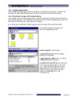
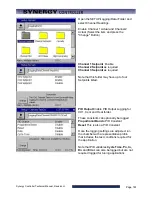
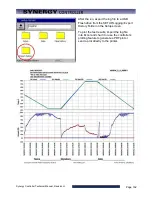
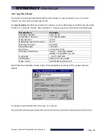
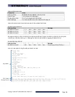
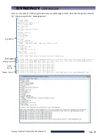
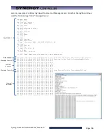
4. Setup Logging; Log interval, log data, log enable. (See the
5. Enter the WebTouch Remote, Cascade Control and Pressure Control Registration keys as
necessary.
Summary of Contents for Synergy Compact
Page 14: ...Synergy Controller Technical Manual Revision H Page 14 2 0 SPECIFICATIONS 2 1 Data Sheet...
Page 71: ...Synergy Controller Technical Manual Revision H Page 71...
Page 106: ...Synergy Controller Technical Manual Revision H Page 106...
Page 123: ...Synergy Controller Technical Manual Revision H Page 123...
Page 141: ...Synergy Controller Technical Manual Revision H Page 141 TE1151 6 Triac Output Board Schematic...
Page 142: ...Synergy Controller Technical Manual Revision H Page 142 TE1708 6 Relay Board Schematic...
Page 188: ...Synergy Controller Technical Manual Revision H Page 188...
Page 274: ...Synergy Controller Technical Manual Revision H Page 274 Synergy Controller Step Syntax...
Page 294: ...Synergy Controller Technical Manual Revision H Page 294...
Page 312: ...Synergy Controller Technical Manual Revision H Page 312...
Page 345: ...Synergy Controller Technical Manual Revision H Page 345...
Page 346: ...Synergy Controller Technical Manual Revision H Page 346...

