Synergy Controller Technical Manual, Revision H
Page 41
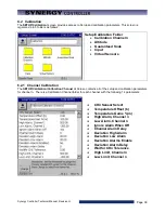
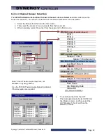
6.2.2 Altitude Value
SETUP\Calibration\Altitude\Altitude Value\
ALT
SETUP\Calibration\Altitude\Altitude Value\
sets the scaling for the pressure channel. Set the altitude value
to 0 for linear scaling for regular pressure transducers. For Granville-Philips transducers, set the parameter
to 10, 11 or 12 for exponential scaling. A Registration Key may be required to access this feature. See
additional details in the
Altitude/Space Chamber Setup section
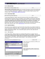
6.2.3 Guaranteed Soak
SETUP\Calibration\Guaranteed Soak\
GS
The Guaranteed Soak feature stops a program from advancing until the process variable is within the
guaranteed soak limits. Range for this is 0 to 50 degrees. This value applies to each setpoint in the program.
As an example, for a setpoint of 100 degrees with a guaranteed soak of 1 degree, the program will wait until
a temperature between 99 and 101 degrees is reached before advancing, regardless of the step time. When
enabled, the Guaranteed Soak feature will affect all setpoint steps in any profile run on the chamber. An
alternative to the system wide Guaranteed Soak setting is the Wait For step which provides soaking on
specific steps of the profile. For example, to guarantee a soak at 100C add a Ramp step to 100C then add a
Wait For step that waits for 100C. See the
of the manual for more information.
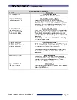
6.2.4 Input Calibration
Each controller input is calibrated and scaled from this folder and sub-folders. Raw calibration calibrates the
controller measurement, either Volts or Ohms. The voltage and scale and engineering scale are set for each
sensor. The input type is selected from the list. The High Resolution Inputs are the most accurate inputs and
typically uses for process variables. The Low Resolution inputs are used for machine parameters like
pressure transducers, etc.
6.2.4.1 RTD Calibration
The Synergy Controller chamber accepts up to two Platinum RTD (Resistance Temperature Detector)
sensors. RTDs are the most linear, stable and reproducible temperature sensors available. Over the years,
both American and European RTD standards have been developed to ensure that RTDs are interchangeable
from manufacturer to manufacturer. Platinum RTDs are specified to standards such as DIN (Deutsch
Institute fur Normung) and JIS (Japanese Industrial Standard). These standards define the RTD
specifications.
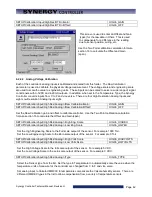
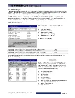
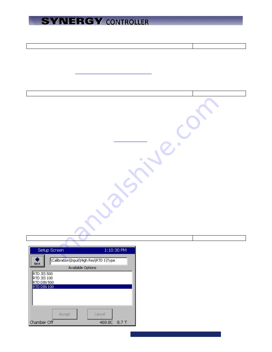
SETUP\Calibration\ Input\High Res\RTD n\Type\
HIGHn_TYPE
Each of the Synergy Controller’s two RTDs can be
set for four types:
RTD JIS 500
RTD JIS 100
RTD DIN 500
RTD DIN 100.
Note: In early software versions, the RTD curve
was set globally so one RTD curve was used for
both sensors.
Summary of Contents for Synergy Compact
Page 14: ...Synergy Controller Technical Manual Revision H Page 14 2 0 SPECIFICATIONS 2 1 Data Sheet...
Page 71: ...Synergy Controller Technical Manual Revision H Page 71...
Page 106: ...Synergy Controller Technical Manual Revision H Page 106...
Page 123: ...Synergy Controller Technical Manual Revision H Page 123...
Page 141: ...Synergy Controller Technical Manual Revision H Page 141 TE1151 6 Triac Output Board Schematic...
Page 142: ...Synergy Controller Technical Manual Revision H Page 142 TE1708 6 Relay Board Schematic...
Page 188: ...Synergy Controller Technical Manual Revision H Page 188...
Page 274: ...Synergy Controller Technical Manual Revision H Page 274 Synergy Controller Step Syntax...
Page 294: ...Synergy Controller Technical Manual Revision H Page 294...
Page 312: ...Synergy Controller Technical Manual Revision H Page 312...
Page 345: ...Synergy Controller Technical Manual Revision H Page 345...
Page 346: ...Synergy Controller Technical Manual Revision H Page 346...

