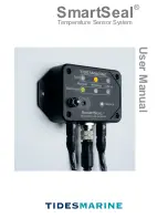
Congratulations on your purchase of the Tides Marine
SmartSeal® Temperature Sensor System. This manual will
describe how the system works, the various system components
and how to operate the system. Detailed information on
Installation can be found in the Installation / Specifications
Manual.
System Overview
The SmartSeal Temperature Sensor System is designed to
compliment Tides Marine’s SureSeal Shaft Seal Systems on
vessels with single or twin engines. Its purpose is to detect and
warn of various vessel conditions which could potentially lead to
shaft seal damage or failure. It is compatible with vessels which
utilize the NMEA 2000 communication protocol for connecting
marine electronics, sensors and display units to a backbone
network for centralized monitoring of various types of vessel
information. It is also designed to operate on non-NMEA 2000
equipped vessels as well on vessels with certain other networks
via a converter (e.g. NMEA 01830).
Functional Overview
The SmartSeal System is comprised of a number of components
designed to work with a wide range of vessel types and
installation needs. At the heart of the system is a Main Control
Unit which is located in the engine compartment. Connected to
this unit are temperature sensors for each shaft seal in use.
Remote Monitoring Units can be connected and placed in other
areas of the vessel as can a remote external siren. In operation,
temperature status data is displayed on both the Main and
Remote unit’s control panels. When connected to a vessel’s
NMEA 2000 onboard network, temperature data is also sent to the
main or auxiliary computer display. In the event that the
temperature of the shaft seal(s) or the engine compartment
exceeds the normal operating range limit, visible and audible
alerts are initiated so that corrective action can be taken.
2
Table Of Contents
External Siren.........................................................................5
System Operation:
Remote Unit............................................................................3-4
Shaft Seal Sensor...................................................................5
Powering.................................................................................6
Operating................................................................................6
Operating States:
Normal State...........................................................................7
Error Indications.....................................................................9
Troubleshooting.....................................................................10
Causes of Alerts......................................................................9
Self-Test Function...................................................................9
System Overview....................................................................2
Functional Overview...............................................................2
System Components:
Main Control Unit....................................................................3-4
Warning State.........................................................................7-8
Critical Alert State...................................................................8

