background image

Remote Monitoring Units (RMU)

The Remote Monitoring Units are display extensions of the Main Control Unit. 
On larger vessels, one or more RMUs are typically installed in locations where 
they can be easily monitored. To afford installation flexibility, two mounting 
configurations are offered: Surface / Bulkhead mount (identical to the Main 
Control Unit), and a panel mount design for installing into Consoles or Helm 
Stations.

The RMU’s front panel display will have the same LED indicators and alarm 
speaker as found on the Main Control Unit.

Main Control Unit
/ NMEA 2000 
Connector

Temp. Status
Indicators

Onboard 
Alarm
Speaker

Remote Unit,
Bulkhead Mount
Twin Engine

P/N TPS-RDBH

Remote Monitoring Unit,
Bulkhead Mount
Single Engine
P/N TPS-RSBH

Remote Unit Monitoring,
Panel Mount
Single Engine
P/N TPS-RSPN

Remote Monitoring Unit,
Panel Mount
Twin Engine
P/N TPS-RDPN

4

System Components

Main Control Unit (MCU)

Mounted in the engine compartment, the Main Control Unit contains a 
microprocessor which is responsible for the systems operation.
The MCU front panel has an onboard audible alarm and silence 
control, ambient temperature sensor and LED temperature status 
indicators. There are single and twin engine models available. Both 
models are identical in size and have flanges for surface mounting. 
Units are ideally positioned on vertical surfaces/ bulkheads which are 
both visually and physically accessible. 

Each MCU has two types of connectors on the bottom of its enclosure. 
The first is used to connect the shaft seal sensor, neutral safety switch 
and optional remote siren.  The second is used for connecting the 
Remote Monitor Unit and 12VDC power source or to connect the 
SmartSeal System to a NMEA 2000 network.  

Main Control Units are IP66 rated (waterproof for heavy spray and brief 
submersion)

Main Control Unit,
Bulkhead Mount
Twin Engine

P/N TPS-BH-TE

PORT Side
Harness
Connector

STBD. Side
Harness
Connector

Ambient Temp.
Sensor

Temp. Status
Indicators

Alarm/Siren
Control

Onboard 
Alarm 
Speaker

Remote Unit
/ NMEA 2000 
Connector

Main Control Unit,
Bulkhead Mount
Single Engine
P/N TPS-BH-SE

3

Summary of Contents for SmartSeal TPS-BH-SE

Page 1: ...User Manual Temperature Sensor System SmartSeal...

Page 2: ...ft Seal Sensor 5 Powering 6 Operating 6 Operating States Normal State 7 Error Indications 9 Troubleshooting 10 Causes of Alerts 9 Self Test Function 9 System Overview 2 Functional Overview 2 System Co...

Page 3: ...It is also designed to operate on non NMEA 2000 equipped vessels as well on vessels with certain other networks via a converter e g NMEA 01830 Functional Overview The SmartSeal System is comprised of...

Page 4: ...are both visually and physically accessible Each MCU has two types of connectors on the bottom of its enclosure The first is used to connect the shaft seal sensor neutral safety switch and optional r...

Page 5: ...ain Control Unit and a panel mount design for installing into Consoles or Helm Stations The RMU s front panel display will have the same LED indicators and alarm speaker as found on the Main Control U...

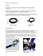
Page 6: ...g Units to the Main control Unit Sensor Mounted On Shaft Seal Injection Fitting Sensor and Clamp on Fitting System Components Shaft Seal Sensor Connected to the Main Control Unit The Shaft Seal Sensor...

Page 7: ...ure Sensor is an autonomous system It continuously monitors shaft seal temperature s and reports results as visual and audible indications on the Main and Remote unit front panels It also broadcasts s...

Page 8: ...g condition Normal Operation Normal state is indicated by the Green LED s being illuminated when the engines are running This indicates that the system is operating with the shaft seal temperature bel...

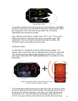
Page 9: ...ith Alarm Siren Sound indicate CRITICAL ALERT condition PORT STBD NORMAL CRITICAL WARNING SILENCE Temperature Sensor System SmartSeal Critical Alert State A Critical Alert is indicated by the Red LED...

Page 10: ...ndicating all internal self tests have passed and the unit is operating correctly In addition the Main Control Unit will beep one or two times indicating it is a single or twin engine unit The Remote...

Page 11: ...on is due to a failure detected in the Main control unit self test which occurs on each power up Other internal issues could cause the self test to fail In this case please contact Technical Support f...

Page 12: ...ll Free Phone 800 420 0949 General Phone 954 420 0949 General Fax 954 420 5234 Order Fax 954 420 0945 WWW TIDESMARINE COM TIDESMARINE innovative products for the marine industry 2018 Tides Marine All...

Reviews: