Page 2
5. RATINGS
The
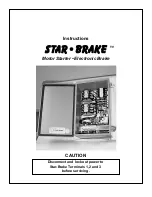
STAR-BRAKE
should be used at its published
horsepower rating. The protective overload is sized for
the nominal motor current, and may not protect a motor of
lower horsepower. For overload rating, see section 7.2.1.
Any application requiring frequent or severe braking, or
operation more often than two stops per minute, may
require a different model
STAR-BRAKE.
Applications involving exceptionally high inertia, such as
press flywheels, extractors, etc., may require models with
longer than the standard 15-second maximum braking
time. For information on applications such as these,
please consult the factory or your local sales representa-
tive.
All
STAR-BRAKE
units may be used in normal ambient
temperatures. The maximum temperature at the hottest
part of the heat sink should not exceed 50 degrees C. At
temperatures below O degrees C, braking levels may
decrease.
STAR-BRAKE
units have internal fuses. These are
special, fast-acting, semiconductor fuses. They must be
replaced with the same type as originally supplied.
THE USE OF IMPROPER FUSES IN THE
STAR-8RAA'fWILL VOID THE WARRANTY!!!!
6. INSTALLATION
6.1 Mounting
The
STAR-BRAKE
may be mounted in any convenient
location, and in. any orientation, although vertical is
preferable. Keep it away from sources of vibration, dust,
dirt and extremes of temperature. Once mounted, it
normally needs no maintenance.
6.2 Wiring
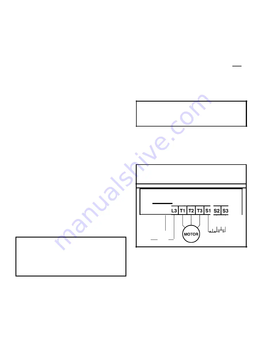
6.3 Control Wiring
1. Connect a dry, momentary, normally closed (Stop)
pushbutton between Terminals S1 and S2.
2. Connect a dry, momentary, normally open (Start)
pushbutton between Terminals S2 and S3.
Note: If a programmable controller is used to control the
Start and Stop function, relay type output modules must
be employed. See section 9.4.
6.4 Power Wiring
WARNING ON THE USE OF
POWER FACTOR CAPACITORS
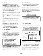
6.4.1
Three Phase Motor
INPUT (LINE POWER) SIDE: Terminal L1, L2, L3
OUTPUT (MOTOR) SIDE:
Terminal T1, T2, T3
Figure
6.4.1
6.4.2
Single Phase Motor
3 Phase Wiring
All wiring to the
STAR-BRAKE
is done to terminals provided.
In general, the wires connected to terminals L1, L2, L3,
T1, T2, T3 must be able to carry the full motor starting and
running current. Wires connected to S1, S2, S3 may be
"control wire" gauge.
Input (Line Power) Side: Terminal L1, Terminal L2
Output (Motor) Side:
Terminal T1, Terminal T.2
Note that for a given voltage and horsepower rating, a
single phase machine will draw greater current than the
three-phase equivalent. Be sure not to exceed
either
the
horsepower or current rating of the
DAR-8/iAl(F.
The STAR-BRAKE will be damaged if power factor
or other capacitors are present across the motor
leads. If capacitors are used, they must be placed
on the LINE side.
Be sure to check if the MOTOR IS ROTATING IN
THE PROPER DIRECTION before operating the
machine. If it is not, interchange the wires con-
nected to Terminals T1 and T3.
,
Stop Start
L1
L2 -
L3
STAR-BRAKE
•
ALL WIRING SHOULD CONFORM
WITH NATIONAL AND LOCAL
ELECTRICAL CODES.
•
BE CERTAIN THAT POWER IS TURNED
OFF AND LOCKED OUT, BEFORE
PROCEEDING WITH ANY WIRING!!!


