Section 22: Connection Setup
T
ieline
Page 225
T E C H N O L O G Y
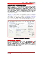
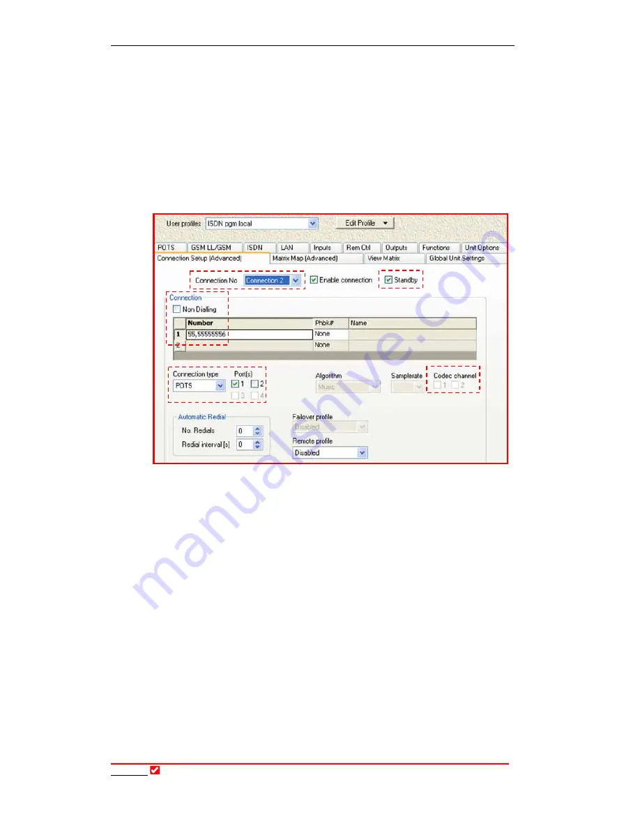
Following is an image showing how you would set up
Connection 2
in your
main profile, as per our example. Note that the
Standby
box is checked, the
Connection type
is POTS and that
Port 1
is checked. All these settings are the
same as those made in the
Failover profile
. In addition the phone Number
matches the POTS Failover profile that is programmed.
The
Codec channel
doesn’t need to be allocated in this connection because it
will not be sending audio until failover is initiated, i.e. it is in
Standby
running
concurrently with the main connection. When failover occurs, the
Failover
profile
settings will be activated and these should have the
Codec channel
allocated.
Figure 63: Failover Connection Dialing and Port Allocation Programmed into a Main Profile
The next image shows the
Failover profile’s
settings. Please note that the
phone
Number
and
Port
settings are the same as in
Connection 2
(shown
previously) of the main ISDN connection. In addition, a codec channel has
been allocated which will facilitate sending a program signal if the failover
profile is activated. Also, please note that the
Remote profile
is set to be the
same profile as the
POTS failover
profile. This is so that the
POTS failover
profile will be loaded onto both codecs as required in the event of failover
being activated.

