348
Genie Distribution User Manual v1.6
© Tieline Pty. Ltd. 2015
29
Appendix A: RS232 and Control Port Wiring
Relays
The codec uses a DB15 connector to facilitate use of four CMOS solid state relays for the control of
equipment, consisting of four relay closures and four opto-isolated outputs.
Inputs
The input signal is referenced to chassis ground, i.e. the ground reference terminal on the
connector is connected the chassis. The input device is a high impedance CMOS device with a
330 ohm pull-up resistor to +5 volts.
Operation is as simple as joining the input pin to the ground terminal. This can be via a remote
relay contact or the open circuit collector of a transistor or FET. DO NOT feed voltages into the
inputs.
Outputs
CMOS field effect transistors switch a low impedance path between the two pins when
activated. These are opto-isolated and floating above ground. It is important to current-limit the
source as damage will result where the current exceeds 100mA peak-to-peak. No more than 48
volts peak-to-peak should be used as a safety precaution. The resistance of the CMOS element
is approximately 25 ohms in the ON state.
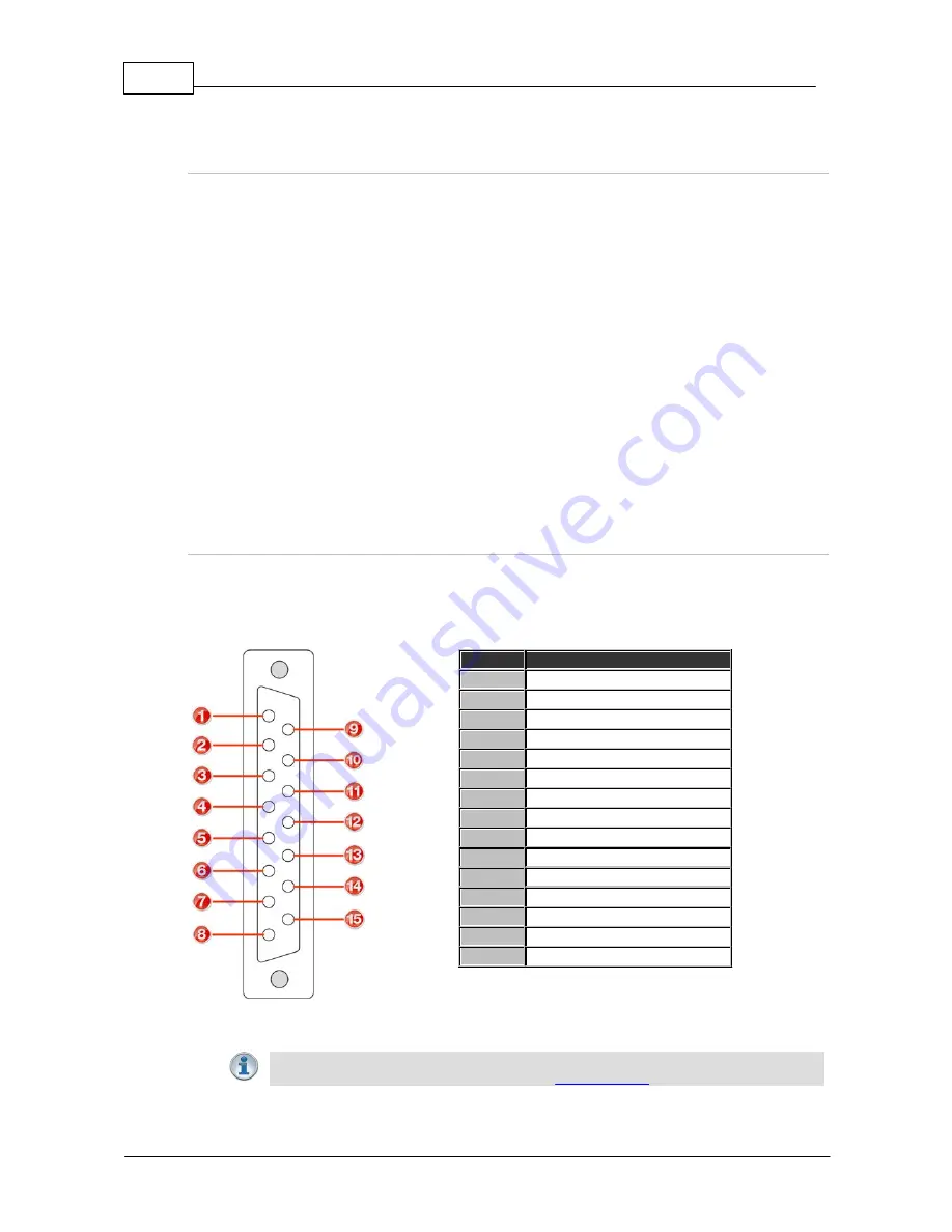
Control Port Pin-outs
A closing contact across Inputs 1-4 to Ground will provide a closing contact on the remote codec
Outputs 1 to 4. If your codec supports multi-unicast connections to multiple codecs, a contact
closure will appear on each of the compatible (non-G3) remote codecs' corresponding contacts. I.e.
Input 1 shorted, Output 1 contacts on all connected codecs closed.
Female DB-15
Codec Connector
Pins
Pin Function
1
Ground
2
Output 4
3
Output 3
4
Output 2
5
Output 1
6
Ground
7
Input 3
8
Input 1
9
Output 4
10
Output 3
11
Output 2
12
Output 1
13
Ground
14
Input 4
15
Input 2
Important Note:
For more information about how to program relay operations with a
PC using the Toolbox Web-GUI, please see
Creating Rules
.


