Pag. 4/15
0CAR6IN019124_Manual_GLH110_Rev_0.3
SOLAR CIRCUIT
Buffer Tank Loading:
The Solar Manifold Pump is activated:
If the Temperature of (
S3
) >
A33
and
Δ
(
S3
-
S2
) >
d02
The Buffer Loading is disabled once the Buffer Comfort Thermostat has been reached on S2 (
A20
).
Manifold and Buffer Safety:
If the Temperature of the Manaifold (
S3
) >
A35
(Manifold Safety Thermostat) the Manifold Pump is turned on again and
fills the Buffer Tank until
A23
high temp. Thermostat has been reached.
Manifold Protection:
If the manifold Temperature (
S3
) >
A36
(Manifold Safety Thermostat) the manifold pump is turned off
Antifreeze:
When this function is enabled (
P09=1
) if the temperature detected by
S3
probe (even while the controller is OFF) falls
below the Antifreeze Thermostat
A34
the manifold pump is turned on for
t04
time at intervals of
t05
time
WOOD INTEGRATION PRIORITY (Hydraulic/Plumbing plants including Buffer Tank)
This feature gives priority to the integration of the fireplace instead of the Gas boiler.
Se
P10
=1 priority is given to the wood fireplace in managing the integration of the Buffer Tank instead if the Gas Boiler.
PUMPS MANAGEMENT WITH PWM CONTROL
P18
and
P19
parameters are used to enable and select the operating mode of the PWM1 and PWM2 signals, to manage the
pumps provided in the hydraulic/plumbing schemes:
PWM1:
P18 = 0 → Disabled; P18 = 1 → Manual;
P18 = 2 → Automatic
PWM2:
P19 = 0 → Disabled; P19 = 1 → Manual;
P19 = 2 → Automatic
PWM Disabled:
The pumps are controlled exclusively via 230V outputs
PWM Manual:
The PWM duty cycle which determines the speed of the pumps is set with the following parameters:
U06 if PWM1 with Heating profile
(Fireplace Pump)
U16 if PWM2 with Heating profile
(Heating Pump)
U26 if PWM2 with Solar profile
(Solar manifold Pump)
Automatic PWM:
In relation to the type of pump, the PWM duty cycle is calculated on the basis of the temperature of the fireplace probe,
high Buffer Tank probe or solar manifold probe and can vary within the following ranges:
Between U01 and U02 if PWM1 with Heating profile (
es. 85 ÷ 5 %)
Between U11 and U12 if PWM2 with Heating profile (
es. 85÷ 5 %)
Between U21 and U22 if PWM2 with Solar profile
(
es. 15 ÷ 95 %)
Fireplace Pump speed change is enabled within the following temperature range:
Between A01 and A01+A80 in heating management
(
ex. if A01=35°C, A80=20°C then range: 35 ÷ 55 °C
)
Between A01 and A01+A81 in DHW management
(
ex. if A01=35°C, A81=15°C then range: 35 ÷ 50 °C
)
Heating Pump Speed change is enabled within the following temperature range:
Between A04 and A04+A82
(
ex. if A04=45°C, A82=20°C then range: 45 ÷ 65 °C
)
Or if the Buffer Tank is present
Between A17 and A17+A82
(
ex. if A17=45°C, A82=20°C then range: 45 ÷ 65 °C
)
Solar manifold Pump speed change is enabled within the following temperature range:
Between A33 and A33+A82
(
ex. if A33=45°C, A82=20°C then range: 45 ÷ 65 °C
)
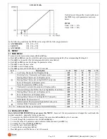
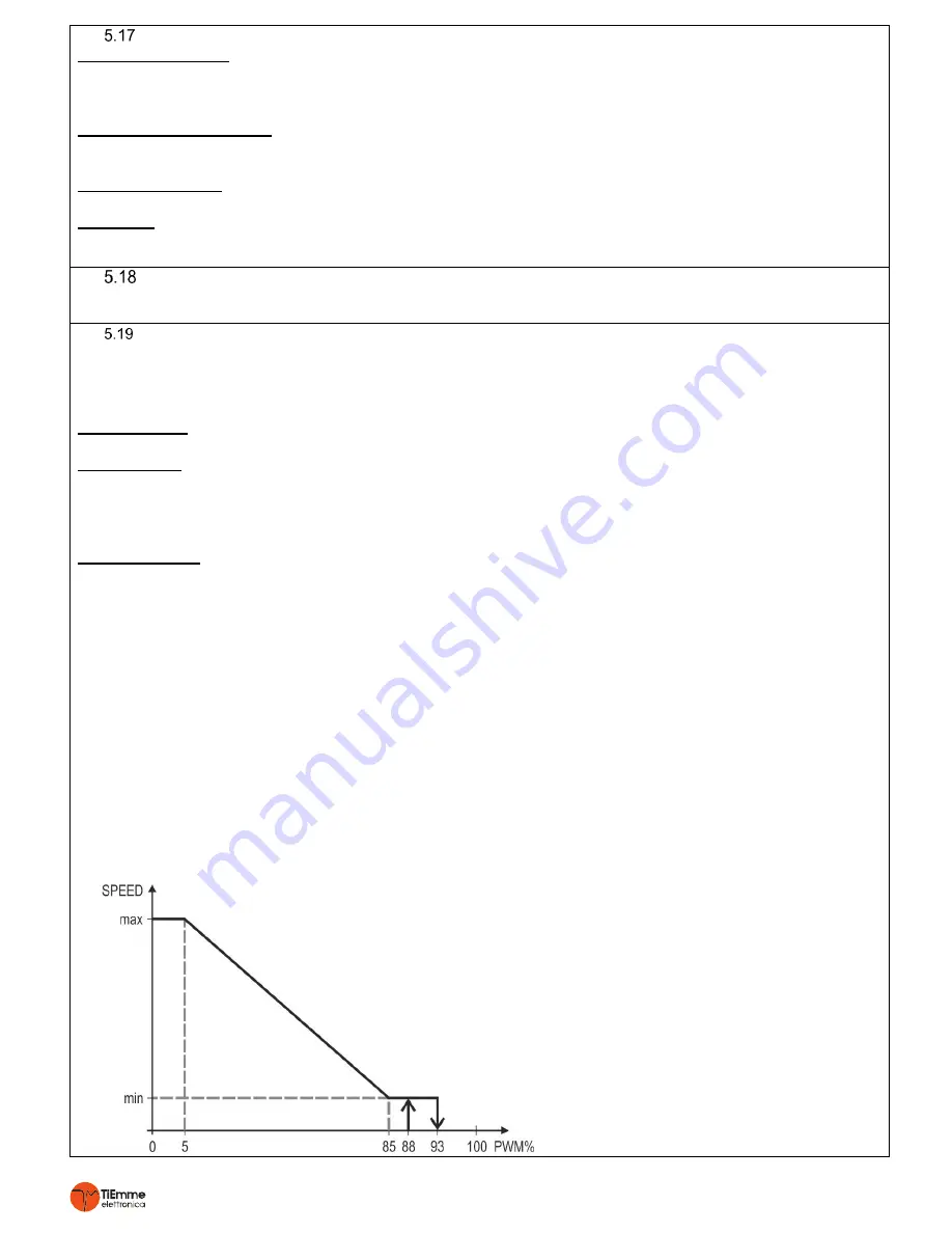
The profile of the PWM signal, Heating or Solar, is selected automatically on the basis of the pump that needs to be
managed and the following are the profiles of the pumps that can be found on the market:
HEATING Profile
On the basis of this profile it is advisable to set
the PWM duty cycle parameters as shown
below:
PWM1
Vmin: U01 <= 85%
Vmax: U02 >= 5%
PWM2
Vmin: U11 <= 85%
Vmax: U12 >= 5%


