Pag. 16 / 70
DMAN802000093-Manual MB250 Hydro Wood-Pellet STD11
DHW Probe
To use this input as a Probe set the parameter
P74
,
P75
or
P76
=8 and
P26
=2, 3, 10, 11.
This probe is an NTC 10K sensor and its range is 0 ÷ 110° C with a precision of 1 °C.
If you don’t connect the probe to the system you’ll read -50 °C, in case of short-circuit you’ll read 110°C.
External Probe
To use this input as a Probe set the parameter
P74
,
P75
or
P76
=7.
This probe is an NTC 10K sensor and its range is -50÷110 °C with a precision of 1 °C. If you don’t connect
the probe to the system you’ll read -50 °C, in case of short-circuit you’ll read 110°C.
Water Pressure Sensor
To the connections 37-38-39 is available the Pressure Sensor to read the boiler’s pressure. It can read from
0 to 3000 mbar. To activate the alarms due over/under pressure of the boiler, set the parameter
A14
=1. In
this case, set the minimum and maximum pressure levels (
SP01
and
SP08
parameters).
Photo Resistance
The probe detects the flame brightness of the brazier. The brightness range goes from 0 to 100. If not
connected the read value is 0. In case of use on input IN8 connect it to pin 44 (signal) and 33 (+5V).
The photo resistance is enabled only in Pellets modality. If the system provides a Wood
modality it is necessary to use also the thermocouple.
Primary Air Flow or Vacuum Sensor
Setting the parameter
P71
it is possible to choice the sensor to connect to the Input IN8.
If
P71
=1 it is possible to connect an Air Primary sensor or a Vacuum sensor; the sensor works on the
combustion parameters (Auger and Combustion Fan). The range is 0÷2000.
In the case of disconnected probe the system will read a speed value of 0. In case of failure adjustment it
shows the message Er17, in case of broken sensor or not connected properly, will appear the message
Er39.
If an Air Primary sensor is used:
Connections:
43=+12V (red wire)
44=SEG (brown wire)
45=GND (black wire)
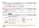
If a Vacuum sensor is used:
has to be placed horizontally through the bracket supplied
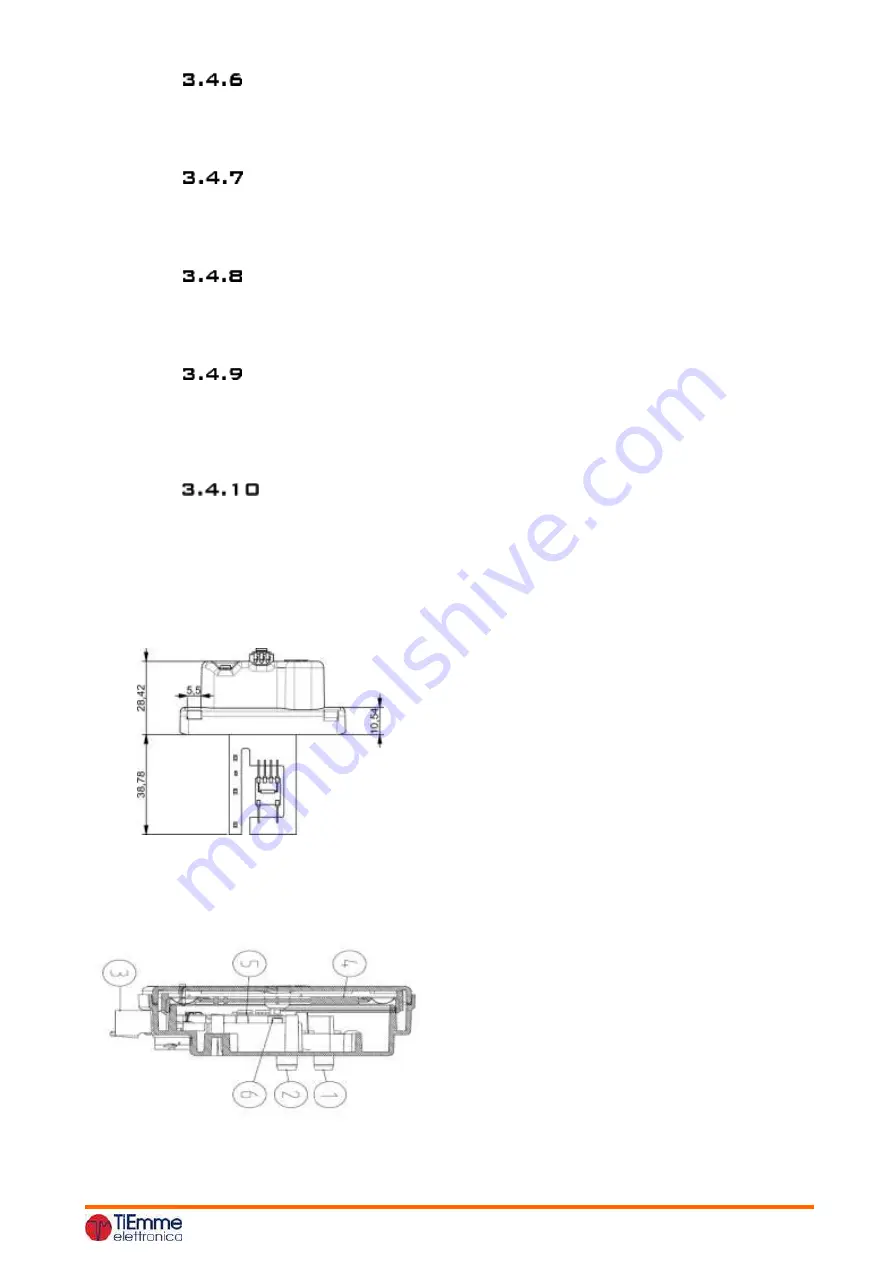
the connections for the pressure reading (see Figure 1 and 2) should be directed downward.
Connections:
43=+12V (red wire)
44=SEG (yellow wire)
45=GND (black wire)
Caption:
1 Connection pressure P1 (high pressure)
2 Connection pressure P2 (low pressure)
3. Electrical connections


