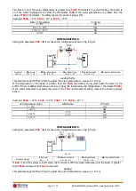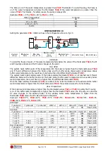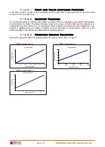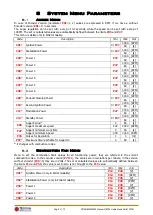
Pag. 51 / 70
DMAN802000093-Manual MB250 Hydro Wood-Pellet STD11
1.
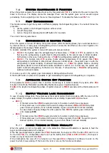
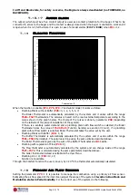
Switch on the System with air flow sensor disabled (parameter
A24
=0). In Run Mode and Modulation
states monitor the air flow speed for each power of the system.
2.
Once found the optimum air flow speed values for each power of the System, start to configure the air
flow regulator setting:
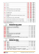
Set values of the air flow for each power (parameters
FL22
÷
FL30
).
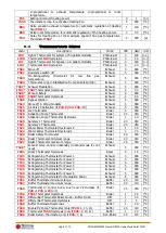
Variation delta of the air flow compared to the set value for each power (parameters
FL52
÷
FL60
).
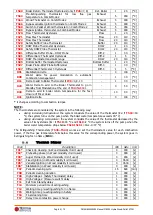
T19
the time how often to regulate the combustion (short is this time, less readings will be done
by the system).
T20
waiting time with sensor fixed out of the minimum or the maximum range, before to go to
regulate another output or before to go in regulation error.
T80
Waiting Time before starts the first regulation.
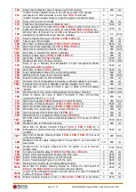
A24
to set which kind of combustion desired.
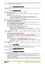
Regulation Step for each Output (
U60
,
C60
)
Regulation order on the selected output (this function will be active if
A24
is set to regulate two
output):
If
A31
=0 the sensor starts to regulate the first output, goes on the next output if needed,
then go back on the first output .
If
A31
=1 the sensor starts to regulate the first output, goes on the next output if needed
and the remain on this output.
System functioning in case of failed output regulation:
if
A25
=0 selected outputs go on working with last values calculated by air flow sensor.
if
A25
=1 air flow sensor has been Reset and restarts for a new regulation attempt.
if
A25
=2 air flow sensor is disabled, selected outputs go on working with default settings
and the display shows the error Er17.
3.
At the end of the set-up procedure, it will be possible to restart the System with Air Flow Sensor turned
on. The first intervention on the system, to stabilize the combustion, will be after
T80
seconds. Then,
the Control board reads air flow speed for
T19
seconds and checks if this value is in the range
FL2X
±(
FL2X
*
FL5X
) for the current System Power. If this does not happen the sensor modifies the set
values for Combustion Fan and/or Auger. Regulations act on the outputs as follows:
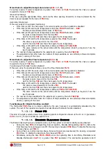
Read Air flow Speed value lower than prefixed range:
The Combustion Fan speed has increased of
U60
up to the value
P30
.
The Auger’s time work/speed has decreased of
C60
up to the value
P27
if the auger is without
inverter or zero if it is with the inverter.
Read Air flow Speed value higher than prefixed range:
The Combustion Fan speed has decreased of
U60
up to the value
P14
.
The Auger’s time work/speed has increased of
C60
up to the value
P05
if the auger is without
inverter or 100 if it is with the inverter.
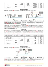
The Regulator functioning can be described into 2 modes:
Single output regulation
(
A24
=1 or 3)
The regulator modifies the set value of one single output and if it can keep the output within
defined limits, the System works normally. If output speed reaches the minimum or the maximum
value, without bringing air flow speed into the limits, the system waits for a period equal to
T20
after that, if the parameter
A25
is equal to 0, the regulator continues with the current data, if
A25
=1 it resets and restarts from the beginning, if
A25
=2 it goes in error, disables and displays
the message Er17.
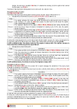
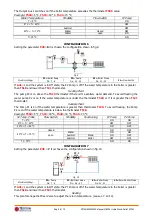
Two outputs regulation
(
A24
=2 or 4)
The regulator modifies the set value of primary output and if it can keep the output within defined
limits, the System works normally. If output speed reaches the minimum or the maximum value,
without bringing air flow speed into the limits, the system waits for a period equal to
T20
after
that the regulation goes on the second output. If also this regulation reaches the minimum or the
maximum value, without bringing air flow speed into the limits, the system waits for a period equal
to
T20
after which, if
A25
=0 the regulator continues with the current data, if
A25
=1 resets and
restarts from the beginning, if
A25
=2 fails, disables itself and displays Er17.
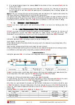
4.
If the Air Flow Regulator is interrupted by random events that force to change the combustion, such as
Periodic Cleaning, then, when the system returns on the previous state, the regulator will wait for a
period equal to
T80
before the first intervention.
5.
If on keyboard display appears the message Er39 the device is damaged, the regulation is disabled and
the outputs, Auger and Fan, will work with the factory settings

