background image


Pag. 14 / 44 


DMAN802000066-SY250 Idro 4/8 Buttons Manual 

O


N


O


F


F


3.2.4


Combustion Recipe Menu 


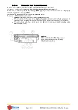
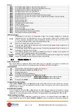
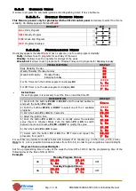
Menu to select the Combustion Recipe. The maximum value is the number of recipes visible to the user. This 
value can be set in Default Settings Menu (parameter 

P04

). If the parameter 

P04

=1 the Menu isn’t visible. 


3.2.5


Remote Keyboard Thermostat Enable Menu 


Menu which allows to enable the Room Thermostat of the Remote Keyboard. It appears only if 

A52

>0. 


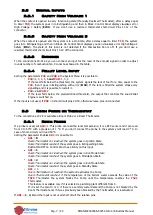
3.2.6


Time and Date Menu 


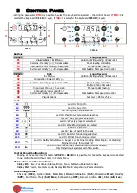
This Menu allows to set time and date. The above display shows hour and minutes, the under display shows 
the day of the week. 


INSTRUCTIONS 

DISPLAY 

Push  the  button 

P3

  or 

K5

  to  enter  editing.  The  selected  value  (hours, 

minutes, days) blinks. To change the value use the 

P2

/

P4

 or 

K3

/

K7

 button. 

Push  the  button 

P3

  or 

K5

  to  switch  to  modify  the  other  parameters.  Push 

again 

P3 

or 

K5

 to save the set value. 

0 7 . 3 3  

      M o  


3.2.7


Summer - Winter Menu 


Menu to modify the plumbing system functioning according to the season. 

Only for CP120 control panel


3.2.8


Remote Control Menu 


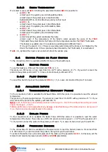
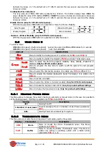
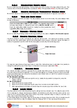
This  Menu  allows  to  enable  and  disable  the  Remote  Control  SYTX.  The  system  can  manage  a  remote 
controller that can communicate with the thermoregulator until 10 meters. Using the remote controller’s 4 

buttons it is possible to switch on/off the thermoregulator and modify the functioning power. 


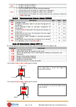
The keys 

Decrease/Increase Power

 aren’t able to work if the combustion power is automatic. It is possible to 

change the combustion power from Power 1 to Number of users power (parameter 

P03

). 


3.2.8.1.


Change Code 


The remote controller’s signal is recognized from  controller board through a code (it is possible to change 
the code using a Self learn procedure). For a correct transmission it is necessary that the remote controller 

and the controller board


have the same transmission code. Default code is 0, but if it is needed to change it, 

follow the procedure below. 

On the Remote Controller: 


Open the battery box and move right the cover, modify the dip-switch’s configuration, close the 
remote controller 

On the Control Board 


Switch off the power supply (230V) 


Switch on the power supply pushing the same time one remote controller’s button 


Wait (approximately 5 seconds) a controller board ‘s acoustic signal that confirms the new code. 


3.2.9


Learn Menu 


This Menu allows to the control board learning the 2Ways remote controller code. The default code is 1000; 
if it is necessary to change code because problems of interference with other remote control, set the new 

code  into  the  Terminal  Radio  2Ways  Menu.  When  the  remote  controller  2Ways  is  ready  to  send  the  new 
code, enter in the control board’s Learn Menu. 

In the bottom display 4 lines blink. Wait for the message of the learning done ‘YES’. If the controller doesn’t 
receive correctly the new code, the display shows the message “NO”. In this case repeat theoperation. 


Off


On 


Power increase 

Power decrease


Summary of Contents for SY250

Page 1: ...Pag 1 44 DMAN802000066 SY250 Idro 4 8 Buttons Manual SY250 IDRO 4 8 BUTTONS MANUAL ...

Page 2: ...ipe Menu 14 3 2 5 Remote Keyboard Thermostat Enable Menu 14 3 2 6 Time and Date Menu 14 3 2 7 Summer Winter Menu 14 3 2 8 Remote Control Menu 14 3 2 9 Learn Menu 14 3 3 SYSTEM MENU 15 3 3 1 Auger Menu TP01 15 3 3 2 Combustion Fan Menu TP02 15 3 3 3 Heatingn Fan Menu TP03 16 3 3 4 Thermostats Menu TP04 16 3 3 5 Timers Menu TP05 17 3 3 6 Default Settings Menu TP06 17 3 3 7 Pressure Sensor Threshold ...

Page 3: ...P 34 6 6 OUTPUT V2 MANAGEMENT 34 6 6 1 Pellet Safety Valve or Auger 2 34 6 6 2 Load Pellet Engine 35 6 6 3 Output Under Thermostat 35 6 6 4 Cleaning Engine 35 6 6 5 Combustion Fan 2 35 6 6 6 Heating Fan 35 6 7 AUXILIARY OUTPUT MANAGEMENT 36 6 7 1 Pellet Safety Valve or Auger 2 36 6 7 2 Load Pellet Engine 36 6 7 3 Output Under Thermostat 36 6 7 4 Cleaning Engine 36 6 8 PERIODIC CLEANING OF BRAZIER ...

Page 4: ...his manual indicates the installation s steps setup functioning and technical characteristics 2 Installation 2 1 Connections In the below picture is showed the connections of the main board and its outputs and inputs Follow the indications of the connection modalities for a correct installation ADVICES For a correct and secure functioning connect always heart connection For a correct operation fol...

Page 5: ...Pag 5 44 DMAN802000066 SY250 Idro 4 8 Buttons Manual ...

Page 6: ...sed 15 16 Auger Motor 17 21 Configurable Auxiliary Output Safety Pellet Valve or Auger 2 External Loading Pellet Engine Cleaning Engine Output Under Thermostat 22 23 24 Valve 25 26 Thermocouple 25 Red 26 Green 27 28 Room Probe or Thermostat 29 30 43 Pellet Sensor 29 GND 30 signal 43 12V 31 32 Boiler Probe 33 34 35 Buffer Probe Flow Switch 36 Non used 37 38 39 Pressure Sensor 40 41 42 Encoder Combu...

Page 7: ...ined threshold the output that controls the Load Pellet Engine is switched on If the input is not used if P09 0 short circuit pins 29 30 otherwise leave pins unconnected 2 3 Room Probe or Thermostat To the connections 27 28 is available a Room Probe or a Room Thermostat 2 3 1 Room Probe If a probe is used set A19 1 This probe can read the room temperature it is a NTC sensor and it can read from 0 ...

Page 8: ...ision of 1 C If you don t connect the probe to the system you ll read 0 C In case of short circuit you ll read 110 C 2 4 2 Flow Switch To use a Flow Switch input set the parameter P26 0 1 5 6 Leave unconnected the pins if not used 2 5 Analogue Inputs 2 5 1 Thermocouple Exhaust Probe To the connections 25 26 is available the Exhaust Probe With this probe it is possible to read the exhaust temperatu...

Page 9: ...s the message Er39 You can use an Air Flow Sensor or a Differential Pressure Sensor If you use a Differential Pressure Sensor Install it horizontally through the mounting bracket supplied The connections for the pressure reading see the picture details 1 and 2 should be lowered To read connect to the P2 connector see picture detail 2 Leave unconnected the P1 connector The connections with the cont...

Page 10: ...e data Combustion Fan speed correction K8 Visualisations Summer Winter choice Leds L1 Led On Pump On L2 Led On Auger On L3 Led On Ignition Resistance On L4 Led On thermostat temperature reached L5 G Led On Daily program seleceted L6 S Led On Weekly program seleceted L7 W Led On Week End program seleceted L8 Led On Valve On L9 Led On lack of pellet in the tank L10 Led On Summer functioning selected...

Page 11: ...sage appears in Run Model and indicates that there is a sanitary water demand It appears only for plumbing systems with a flow switch Ignition Block The message appears if the system is turned off during Ignition after Preload by an external device the system will stop only when it goes in Run Mode 3 1 User Menu 1 Boiler Thermostat Menu which allows to modify the Boiler Thermostat s value It is po...

Page 12: ... C r o n M o d E Menu to select the Chrono s program modality Daily Weekly Week End or disabled Only for CP110 control panel P r o G Menu to program the time slots to switch on off the system for each program modality r i c E Menu to select the Combustion Recipes It is visible only if P04 is different to 1 r E M Menu to enable the Remote Keyboard s Room Thermostat It is visible only if A52 0 o r o...

Page 13: ...s For each program it is necessary to set the time on and the time off DESCRIPTION DISPLAY 1 Scroll with the buttons P2 P4 or K3 K7 until the wished Submenu and push the button P3 or K5 G i o r n 2 Push the buttons P2 P4 or K3 K7 to select one of the 3 available programs 1 I M o 3 Push the button P1 or K4 for 3 seconds 0 0 0 0 1 I M o 4 Select the ignition time 5 Push the button P3 or K5 to enter ...

Page 14: ...crease Increase Power aren t able to work if the combustion power is automatic It is possible to change the combustion power from Power 1 to Number of users power parameter P03 3 2 8 1 Change Code The remote controller s signal is recognized from controller board through a code it is possible to change the code using a Self learn procedure For a correct transmission it is necessary that the remote...

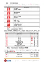
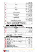
Page 15: ... User s Menu each value is a functioning power If a value is set to 0 seconds the Auger is disabled for the corresponding power The Auger regulation can be set with a step of 0 1 seconds Code Description Min Max Unit C01 Ignition Power 0 60 s C02 Stabilisation Power 0 60 s C03 Power 1 P27 60 s C04 Power 2 P27 60 s C05 Power 3 P27 60 s C06 Power 4 P27 60 s C07 Power 5 P27 60 s C08 Power 6 P27 60 s ...

Page 16: ...Fan Menu TP03 Menu to set the Heating Fan parameters Set these parameters if P44 6 Code Description Min Max Unit F01 Power 1 0 230 Volt F02 Power 2 0 230 Volt F03 Power 3 0 230 Volt F04 Power 4 0 230 Volt F05 Power 5 0 230 Volt F06 Power 6 0 230 Volt P06 Heating management 1 heating power is the same of combustion power 2 heating power is proportional to the exhaust temperature 3 heating power is ...

Page 17: ...ty 0 900 s T16 Final Cleaning Time 0 900 s T17 Delay time Combustion Power Change 0 900 s T18 Delay time Combustion Power Change in exit from Ignition 0 900 s T22 Delay time to enter in Standby 0 900 s T23 Pellet tank charging time over minimum level used if P44 or P48 2 0 9900 s T24 Length signalling of fuel lack if P44 and P48 1 3 4 or Pellet tank charging time over minimum level if P44 or P48 2...

Page 18: ...n is Off 1 During Ignition the Heating Fan is On A10 0 From Extinguishing state it s not possible to go directly to Ignition first the system goes into Recover Ignition and then goes into Ignition 1 From Extinguishing state it s possible to go directly to Check Up A11 0 If room temperature is under Room Thermostat the Heating Fan is Off 1 If room temperature is over Room Thermostat the Heating Fan...

Page 19: ...30 C D08 Water delta for power modulation in automatic combustion management 1 30 C D23 Water Delta to add to the Boiler Thermostat to go in Standby from Modulation at the end of T43 if A13 1 0 50 C 3 3 10 Counters Menu TP11 Menu that allows the control of the counters useful for the diagnosis of the system s life Submenu Description Co 01 Total time system feeding Co 02 Activity time system time ...

Page 20: ...900 C Th43 Modulation Power 5 900 C 3 3 13 Primary Air Flow Sensor Menu TP16 Menu to set the Air Flow Regulator parameters all parameters are referred to the current recipe it has 4 Submenu 1 FL01 Enables Code Description Min Max Unit A24 0 Regulator disabled 1 Combustion Fan speed regulation 2 Combustion fan speed regulation Auger 3 Auger On time regulation 4 Auger Combustion fan speed regulation...

Page 21: ...PM U43 Maximum speed for Power 2 0 230 Volt 300 2800 RPM U44 Maximum speed for Power 3 0 230 Volt 300 2800 RPM U45 Maximum speed for Power 4 0 230 Volt 300 2800 RPM U46 Maximum speed for Power 5 0 230 Volt 300 2800 RPM U47 Maximum speed for Power 6 0 230 Volt 300 2800 RPM U50 Maximum speed for Modulation Power 0 230 Volt 300 2800 RPM U60 Regulation Step 5 100 Volt 10 500 RPM 4 FL04 Auger Regulatio...

Page 22: ...0 230 Volt F08 Power 6 0 230 Volt F09 Periodic Cleaning Power 0 230 Volt F10 Second Ignition Power 0 230 Volt F11 Modulation Power 0 230 Volt F23 Extinguishing Power 0 230 Volt 3 3 15 Restore Default Parameters Menu TP26 This feature allows to save the parameters set by the manufacturer as the default parameters to be restored in case the local welfare or installers have made changes that lead to ...

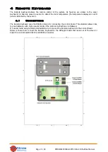
Page 23: ... detected by the sensor 4 1 Connections The Remote Keyboard uses the RS485 protocol for connecting the control board This standard allows links to great distance with high noise immunity if the protocol instructions are followed It is recommend using twisted and shielded wire to connect the Remote Keyboard to the Control Board Below is shown how connect the Remote Keyboard to the SYPlug02 board th...

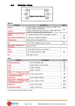
Page 24: ...on Menu Esc Function Exit managed pushing the button P1 Reset System Maintenance 2 Function Reset T67 timer Menu Function Enter in Menu or in a Submenu P3 Modify Enter in modify mode into a Menu Set Save data in a Menu Leds Function Description Led Heating Resistance Led On Resistance ON L1 Auger Led On Auger in the On interval L2 Pump Led On Pump ON L3 Valve Led On Valve ON L4 Output V2 configure...

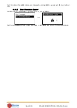
Page 25: ...consists of the name the minimum and maximum set the current value Set Exhaust Temp 103 Boiler Temp 55 Buffer Temp 55 Room Temp 35 Pressure 1548 Air Flow 680 Auger 2 5 Product Code 395 0000 FSYSD01000114 0 0 FSYSF01000158 0 0 FSYSD01000102 0 0 FSYSF01000134 0 0 Exhaust Temperature C Boiler Temperature C Buffer Temperature C visible only if P26 2 3 4 Pressure mbar Air Flow cm s visible only if A24 ...

Page 26: ...y This Menu allows to disable the ignition extinguishing of the system by chrono choice the modality Daily Weekly or Week End to switch on and off the stove or boiler If a chrono modality is set on main frame appears the relating symbol D Daily W Weekly We Week End Procedure Description Buttons Display Modify current modality the selected modality blinks P3 Select the favourite mode P4 e P6 Cancel...

Page 27: ...t 6 30 The 3 programs modality are saved separately for example if it is set the daily mode the others mode aren t modified IMPORTANT after the Chrono programming to switch on the system by Chrono it is necessary to enable the desired mode Daily Weekly or Week End from Modality Menu 4 3 3 Time and Date Menu This Menu allows to set time and date Push the button P4 and P6 to select hours minutes yea...

Page 28: ...e contrast P3 to save and exit P1 to exit without save 4 4 2 Set Minimum Light This Menu allows to set the display light when you don t push any button Push the buttons P4 and P6 to increase or decrease the light P3 to save and exit P1 to exit without save Set Contrast Set Minimum Light Set Minimum Light 9 5 ...
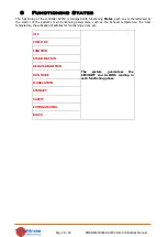
Page 29: ...aracterised by the control of the system s main functioning parameters such as the Exhaust temperature the room temperature the activation of safeties for functioning errors etc OFF The system guarantees the SECURITY and ALARMS reading in each functioning phase CHECK UP IGNITION STABILISATION RECOVER IGNITION RUN MODE MODULATION STANDBY SAFETY EXTINGUISHING BLOCK ...

Page 30: ...otherwise ON Exhaust Temp Th06 thermostat goes in Stabilisation Control at the end of T05 timer If Exhaust Temp Th06 thermostat the system goes in Stabilisation if Exhaust Temp Th06 thermostat the system tries again Ignition from Variable Phase in case of finished number of attempts it goes in Extinguishing with error Er12 If the parameters P44 1 or P48 1 these phase will start at the end of timer...

Page 31: ... Th03 thermostat or Exhaust Temp Extinguishing Thermostat for the used power starts Timer T14 of pre extinguishing User Power User Power OFF Water Temp Boiler Thermostat or Exhaust Temp Th07 Thermostat or Room Temp Room Thermostat and A01 1 or Room Temp Remote Room Thermostat and A52 1 This condition is true if there is a sanitary water demand if it is selected a plumbing system with Flow Switch o...

Page 32: ...mostat and Room Temp Room Thermostat and A01 1 and Room Temp Remote Room Thermostat and A52 1 goes in Run Mode Control at the end of T14 timer Goes in Extinguishing with error Er03 5 8 Standby PHASE Timer Control Thermostat Combustion Resistance Fan Auger Extinguishing T13 Extinguishing of combustion starts Timer T13 P23 OFF OFF Final cleaning T16 At the end of timer T13 if Exhaust Temp T28 thermo...

Page 33: ...ise C03 Exhaust Temp Th08 thermostat and Water Temp Th25 thermostat goes in Modulation Control at the end of T15 timer Goes in Extinguishing with error 5 10 Extinguishing PHASE Timer Control Thermostats Combustion Resistance Fan Auger Wait T13 Exhaust Temp Th01 Thermostat starts Timer T13 P23 OFF OFF Final Cleaning T16 Exhaust Temp Th01 Thermostat and T13 finished starts Timer T16 Max Speed Contro...

Page 34: ...r functioning of the system The display shows the message Service and the system goes in Block To unblock it is necessary to reset the counters To disable this feature set T66 0 6 4 System Maintenance 2 Function When the system exceeds the working hours set by the parameter T67 it is notify the user to clean the boiler or the stove The display shows the message Clean and the system gives out an ac...

Page 35: ...Combustion Fan 1 6 6 6 Heating Fan If the parameter P44 6 the output is configured as a Heating Fan It has the following functioning If exhaust temperature is greater than Thermostat T07 the Fan goes at maximum power 230V If the user set a power different from 0 o it will be On only if Exhaust Temperature is greater than Th05 Thermostat o In Modulation for Room Thermostat if A11 0 the fan is Off i...

Page 36: ...e T08 with a repetition time equal to T07 timer During the cleaning phase the Exhaust Fan goes to at U09 power and the Auger at C09 6 9 Primary Air Flow Sensor The Control Board is designed for reading a Combustion Air Flow Sensor Estimating the air flow speed of the inlet it can adjust the scope of the system It works in Run Mode and Modulation states For the correct use of the system do the foll...

Page 37: ... can be described into 2 modes Single output regulation A24 1 or 3 In this case the controller regulate the power of one output and if the target is reached the System works normally If output speed reach the minimum or the maximum value without bring air flow speed into the limits the system waits for a period equal to T20 after which if the parameter A25 is equal to 0 continue with the current d...

Page 38: ...perature is greater than Th19 Thermostat To avoid freezing the Pump is On if the water temperature is below the thermostat Th18 If the water temperature exceeds the value of the Th21 thermostat for safety reasons the Pump is always active Sanitary Water Plant When there is a water demand for domestic use and the water temperature in the boiler exceeds the value of Th19 thermostat or the water temp...

Page 39: ... water temperature in the boiler doesn t exceed the value of Boiler Thermostat Th58 and the difference between the read temperature by probe S1 and S2 probe is greater than the Th57 thermostat The Pump is On if the water temperature is greater than Th19 Thermostat To avoid freezing the Pump is On if the water temperature is below the thermostat Th18 If the water temperature exceeds the value of th...

Page 40: ...ermostat If water temperature exceeds the value of the Th21 thermostat for safety reasons the Pump P2 is always on Example Th18 5 C Th19 65 C Th20 50 C Th21 70 C Th57 5 C Th58 55 C Temp Probe S1 Temp Probe S2 Modality Differential Pump P2 Pump P1 T 5 C OFF ON 5 C T 50 C OFF OFF 50 C T 65 C T 55 C 5 C OFF OFF 5 C ON OFF T 55 C 5 C OFF OFF Winter 5 C OFF OFF Summer 5 C ON OFF 65 C T 70 C T 55 C 5 C ...

Page 41: ...mp T 5 C ON 5 C T 40 C OFF 40 C T 70 C Summer OFF Winter Close OFF Winter Open ON T 70 C ON CONFIGURATION 6 Setting the parameter P26 6 it is chosen the configuration shown in fig 9 fig 9 Heating Plant Pump P2 is on above the Th19 thermostat if there isn t a sanitary water demand To avoid the water freezing pump P2 is on if water temperature is under Th18 thermostat or over Th21 thermostat Sanitar...

Page 42: ...tion In the plumbing system in which the Flow Switch is present if there is a domestic water demand the Sanitary Function starts the Boiler Thermostat becomes equal to Th21 Thermostat s value and the combustion is controlled by this value When there isn t required the Sanitary Function will stop at the end of T68 timer 6 11 Sensor Pressure Selection Setting the parameter P20 it is possible to sele...

Page 43: ... error code Stop to start Extinguishing from system On The Modem sends back a message to the number from which it received the command with a status and a possible alarm error code Status to ask the system s State The Modem sends back a message to the number from which it received the command with a status and a possible alarm error code Learn to learn the number to send an SMS in case of Block If...

Page 44: ...nput Safety Thermostat External Rearmed Thermostat INPUTS Thermocouple K T 0 500 C 2 Conn Room Probe Analogue NTC T 0 50 C 2 Conn Boiler Probe Analogue NTC T 0 110 C 2 Conn Buffer Probe Analogue NTC T 0 110 C 2 Conn Pressure switch HV N C 2 Conn Safety Thermostat HV N C 2 Conn Flow Switch ON OFF N A 2 Conn Air Flow sensor Analogue F 0 20 m s 3 Conn Pressure Sensor Analogue P 0 3 bar 3 Conn Encoder...

Reviews: