Pag. 37 / 44
DMAN802000066-SY250 Idro 4/8 Buttons Manual
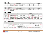
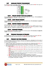
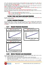
Minimum e maximum range for each output:
Output
Min Regulation
Max Regulation
Combustion Fan
U22
,
U23
,
U24
,
U25
,
U26
,
U27
,
U30 U42
,
U43
,
U44
,
U45
,
U46
,
U47
,
U50
Auger
C22
,
C23
,
C24
,
C25
,
C26
,
C27
,
C30
C42
,
C43
,
C44
,
C45
,
C46
,
C47
,
C50
Regulation Step for each Output (
U60
for Combustion Fan,
C60
for
Auger)
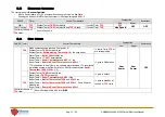
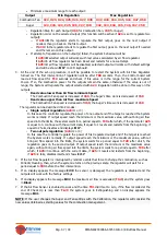
Regulation order on the selected output (this function will be active if
A24
is set to regulate two
output):
If
A31
=0
the regulator starts to regulate the first output, goes on the next output if
needed, then go back on the first output .
If
A31
=1
the regulator starts to regulate the first output, goes on the next output if needed
and the remain on this output.
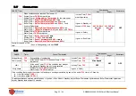
If attempt of regulation on the output(s) failed, the system behaviour will be:
if
A25
=0
selected output will works with last values calculated by air flow regulator.
if
A25
=1
air flow regulator has been Reset and restarts for a new attempt.
if
A25
=2
air flow regulator will be disabled, selected output will works with default settings
and will be shown
Er17
on LCD keyboard.
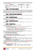
3.
At the end of the set-up procedure, it will be possible to restart the System with Air Flow Regulator
turned on. The first intervention of regulation will be after
T80
seconds. Then, the Control board will
read air flow speed for
T19
seconds and check if this value is in the range for the current System
Power. If so, the combustion power for the outputs remain the same, otherwise if the value is out of
range, the System will regulate the output selected with
A24
. Regulation will be done in this way on the
outputs:
Read value lower than Air flow minimum Speed
The Combustion Fan speed is increased of
U60
, the Auger’s time work is decreased of
C60
Read value upper than Air flow maximum Speed
The Combustion Fan speed is decreased of
U60
, the Auger’s time work is increased of
C60
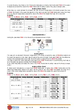
The regulator can be described into 2 modes:
Single output regulation
(
A24
=
1 or 3)
In this case the controller regulate the power of one output and if the target is reached the System
works normally. If output speed reach the minimum or the maximum value, without bring air flow
speed into the limits, the system waits for a period equal to
T20
after which, if the parameter
A25
is equal to 0, continue with the current data, if equal to 1 resets and restarts from the beginning, if
equal to 2 fails, disables and displays
Er17
.
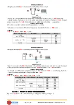
Two outputs regulation
(
A24
=
2 or 4)
In this case the controller regulate the power of first regulated output and if the target is reached
the System works normally. If output speed reach the minimum or the maximum value, without
bring air flow speed into the limits, the system waits for a period equal to
T20
after which, the
regulation goes on the second output. If output speed reach the minimum or the maximum value
again, without bring air flow speed into the limits, the system waits for a period equal to
T20
after
which, if
A25
=0 continue with the current data, if
A25
=1 resets and restarts from the beginning,
if
A25
=2 fails, disables itself and shows
Er17
.
4.
If the Air Flow Regulator is interrupted by random events that force to change the combustion, such as
Periodic Cleaning, then, when the system returns on the previous state, the regulator will wait for a
period equal to
T80
before the first intervention.
5.
If on display appears the message
Er39
the sensor is damaged, the regulation is disabled and the
outputs will work with the factory settings
6.
If on display appears the message
Er42
the maximum air flow is exceeded (
FL40
) and the system goes
in
Block
7.
If the Air Flow Sensor is enabled to work and the time
T01
didn’t set to zero, if the flow recorded at the
end of Check Up is less than
FL20
the system goes in Extinguishing and on display appears the
message
Er41
.
NOTE
: If the user changes the Auger and Fan settings with the Calibration, the regulator will consider the
new values obtained as starting values for the combustion management.

