Pag. 44 / 44
DMAN802000066-SY250 Idro 4/8 Buttons Manual
7
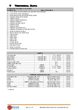
Technical Data
Temperature Controller Code: SY250
Revision: 0.1
Date: 13/04/2012
Power supply 230Vac 50/60Hz with protection fuse 5A delayed
Control Panel with 8 digit display
Management Ignition and Extinguishing system
Regulation Exhaust Thermostat
Activation Auger
Activation Ignition Resistance
Activation Output V2
Activation Auxiliary Output
Activation Pump
Activation Valve
Regulation Combustion Fan
Regulation Modulation and Standby function
Safety and alarms functions
Signal functions and system state
Exhaust Probe
Boiler Probe
Buffer Probe
Room Probe
Pellet Sensor
Air Flow sensor
External Thermostat
Flow Switch input
Safety Thermostat
External Rearmed Thermostat
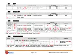
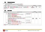
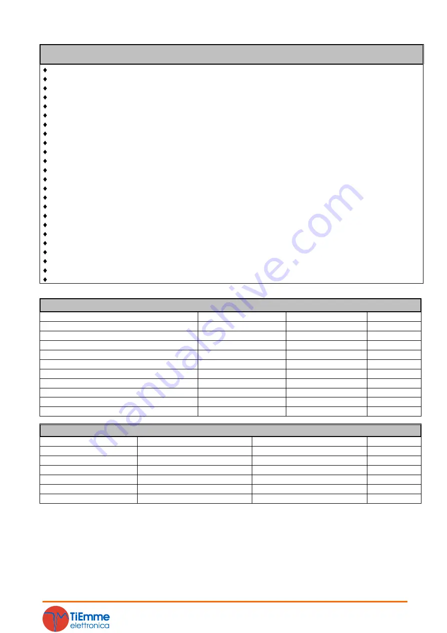
INPUTS
Thermocouple
K
T = 0 – 500 °C
2 Conn.
Room Probe
Analogue NTC
T = 0 – 50 °C
2 Conn.
Boiler Probe
Analogue NTC
T = 0 – 110 °C
2 Conn.
Buffer Probe
Analogue NTC
T = 0 – 110 °C
2 Conn.
Pressure switch (HV)
N. C.
2 Conn.
Safety Thermostat (HV)
N. C.
2 Conn.
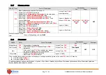
Flow Switch
ON/OFF
N. A.
2 Conn.
Air Flow sensor
Analogue
F = 0 – 20 m/s
3 Conn.
Pressure Sensor
Analogue
P = 0 – 3 bar
3 Conn.
Encoder*
Digital
3 Conn.
Pellet Sensor
ON/OFF
N.C.
3 Conn.
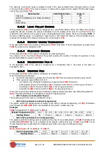
OUTPUTS (maximum load 5 A)
Combustion Fan
Regulation with Triac
Feed Line (Max 0.8 A)
2 Conn.
Auger
ON/OFF with Triac
Feed Line (Max 0.8 A)
2 Conn.
Igniter
ON/OFF with Relay
Feed Line (Max 2 A)
2 Conn.
Output V2
ON/OFF or Regulation with Triac
Feed Line (Max 0.8 A)
2 Conn.
Pump
ON/OFF with Triac
Feed Line (Max 0.8 A)
2 Conn.
Valve
ON/OFF with Relay
Feed Line (Max 2 A)
2 Conn.
Auxiliary Output
ON/OFF with Relay
Free Contact (Max 2 A)
2 Conn.
* if present

