7.3
Extension Connector
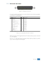
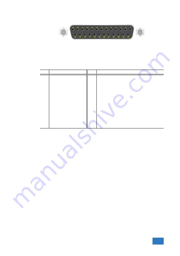
Figure 7.4: Extension connector
To connect to the Handyscope HS4 a 25 pin female D-sub connector is available,
containing the following signals:
Pin
Description
Pin
Description
1
Ground
14
Ground
2
Reserved
15
Ground
3
External Power in DC
16
Reserved
4
Ground
17
Ground
5
+5V out, 10 mA max.
18
Reserved
6
Ext. sampling clock in (TTL)
19
Reserved
7
Ground
20
Reserved
8
Ext. trigger in (TTL)
21
Reserved
9
Data OK out (TTL)
22
Ground
10
Ground
23
I
2
C SDA
11
Trigger out (TTL)
24
I
2
C SCL
12
Reserved
25
Ground
13
Ext. sampling clock out (TTL)
Table 7.2: Pin description Extension connector
All TTL signals are 3.3 V TTL signals which are 5 V tolerant, so they can be connected
to 5 V TTL systems.
Pins 9, 11, 12, 13 are open collector outputs. Connect a pull-up resistor of 1 kOhm
to pin 5 when using one of these signals.
Rear panel
21
Summary of Contents for Handyscope HS4
Page 1: ...Handyscope HS4 User manual TiePie engineering...
Page 6: ......
Page 17: ...Figure 4 3 Driver install Finished Driver installation 13...
Page 18: ...14 Chapter 4...
Page 20: ...16 Chapter 5...
Page 22: ...18 Chapter 6...
Page 26: ...22 Chapter 7...
Page 30: ...26 Chapter 8...
Page 32: ...TiePie engineering Handyscope HS4 instrument manual revision 2 27 February 2020...

