Front panel
6
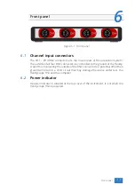
Figure 6.1: Front panel
6.1
Channel input connectors
The CH1 – CH4 BNC connectors are the main inputs of the acquisition system.
The outside of all four BNC connectors is connected to the ground of the Handy-
scope HS4. Connecting the outside of the BNC connector to a potential other than
ground will result in a short circuit that may damage the device under test, the
Handyscope HS4 and the computer.
6.2
Power indicator
A power indicator is situated at the top cover of the instrument. It is lit when the
Handyscope HS4 is powered.
Front panel
17
Summary of Contents for Handyscope HS4
Page 1: ...Handyscope HS4 User manual TiePie engineering...
Page 6: ......
Page 17: ...Figure 4 3 Driver install Finished Driver installation 13...
Page 18: ...14 Chapter 4...
Page 20: ...16 Chapter 5...
Page 22: ...18 Chapter 6...
Page 26: ...22 Chapter 7...
Page 30: ...26 Chapter 8...
Page 32: ...TiePie engineering Handyscope HS4 instrument manual revision 2 27 February 2020...

