background image

Handyscope HS6 DIFF

User manual

TiePie engineering

Summary of Contents for Handyscope HS6 DIFF Series

Page 1: ...Handyscope HS6 DIFF User manual TiePie engineering...

Page 2: ...rous Copyright 2020 TiePie engineering All rights reserved Revision 2 27 February 2020 Despite the care taken for the compilation of this user man ual TiePie engineering can not be held responsible fo...

Page 3: ...15 3 6 Probe compensation 15 4 Driver installation 19 4 1 Introduction 19 4 2 Computers running Windows 10 19 4 3 Computers running Windows 8 or older 19 4 3 1 Where to nd the driver setup 19 4 3 2 E...

Page 4: ...i cations 33 9 1 Acquisition system 33 9 2 Acquisition system continued 34 9 3 Trigger system 35 9 4 Power 35 9 5 Multi instrument synchronization 35 9 6 Probe calibration 35 9 7 Physical 36 9 8 I O c...

Page 5: ...y be performed by quali ed personnel Avoid working alone Observe all indications on the Handyscope HS6 DIFF before connecting any wiring Check the probes test leads for damages Do not use them if they...

Page 6: ......

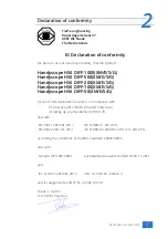
Page 7: ...G for which this declaration is valid is in compliance with EC directive 2011 65 EU the RoHS directive including up to amendement 2019 178 and with EN 55011 2016 A1 2017 IEC 61000 6 1 2019 EN EN 5502...

Page 8: ...health if improperly handled at the Handyscope HS6 DIFF s end of life In order to avoid release of such substances into the environment and to reduce the use of natural resources recycle the Handysco...

Page 9: ...el Resolution Channels HS6D 1000 HS6D 500 HS6D 200 HS6D 100 HS6D 50 8 bit 1 ch 1 GSa s 500 MSa s 200 MSa s 100 MSa s 50 MSa s 2 ch 500 MSa s 200 MSa s 100 MSa s 50 MSa s 20 MSa s 3 or 4 ch 200 MSa s 1...

Page 10: ...This is useful when surfaces are oxidized and your probe cannot get a good electrical contact Simply activate the SureConnect and you know whether there is contact or not Also when back probing connec...

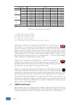
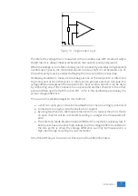
Page 11: ...by connecting one of the channels to one point and another channel to the other point and then use the math function CH1 CH2 in the oscilloscope to display the actual voltage di erence There are some...

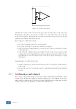
Page 12: ...rential input is high If both points have a relative high voltage but the voltage di erence between the two points is small the volt age di erence can be measured in a low input range resulting in a h...

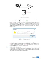
Page 13: ...short circuits to ground Also a warning dialog is shown Figure 3 4 SafeGround warning Once the short circuit is removed SafeGround can be enabled again SafeGround protects your scope your computer and...

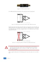
Page 14: ...ble to be used with a di erential input Using these on a di erential input will have a negative e ect on the CMRR and will introduce measurement errors Figure 3 7 Standard probe is mismatch with di er...

Page 15: ...d to signi cant measurement errors Use attenuating oscilloscope probes instead 3 1 3 Di erential test lead The Handyscope HS6 DIFF comes with a special di erential test lead This test lead is speciall...

Page 16: ...lt in gure 3 9 Figure 3 9 connecting the samples 3 3 Sampling rate The rate at which the samples are taken is called the sampling rate the number of samples per second A higher sampling rate correspon...

Page 17: ...uency is 1250 Hz the following signal frequencies will be present in the output data Multiple of sampling rate 1250 Hz signal 1250 Hz signal 1000 1000 1250 250 1000 1250 2250 0 0 1250 1250 0 1250 1250...

Page 18: ...aliasing always start measuring at the highest sampling rate and lower the sampling rate if required 3 4 Digitizing When digitizing the samples the voltage at each sample time is converted to a number...

Page 19: ...ts available in the input signal will arrive at the input circuit and will be measured In the setting AC a capacitor will be placed between the input connector and the input circuit This capacitor wil...

Page 20: ...time a probe is used on an other channel or an other oscilloscope the probe must be adjusted Therefore the probe is equiped with a setscrew with which the parallel capacity of the attenuation network...

Page 21: ...Figure 3 15 over compensated Introduction 17...

Page 22: ...18 Chapter 3...

Page 23: ...puters running Windows 8 or older The installation of the USB driver is done in a few steps Firstly the driver has to be pre installed by the driver setup program This makes sure that all required les...

Page 24: ...cope HS6 DIFF is disconnected from the computer prior to starting the driver install utility When the Handyscope HS6 DIFF is used with an external power supply this must be disconnected too Clicking I...

Page 25: ...Figure 4 3 Driver install Finished Driver installation 21...

Page 26: ...22 Chapter 4...

Page 27: ...ted portable computers or bus powered USB hubs do not supply enough current The exact value at which the power is switched o varies per USB con troller so it is possible that the Handyscope HS6 DIFF f...

Page 28: ...is controlled by Microsoft Windows and is not caused by TiePie engineering 5 4 Operating conditions The Handyscope HS6 DIFF is ready for use as soon as the software is started How ever to achieve rate...

Page 29: ...ed at the beginning and end of the bus The high speed sampling bus takes care that each Handyscope is fully synchronized to ensure that even at the highest sampling rate the instruments operate at the...

Page 30: ...ith a deviation of 0 ppm Figure 6 3 Multiple Handyscope HS6 DIFFs combined A 20 channel instrument is easily made by connecting ve Handyscope HS6 DIFF s to each other When combining one or more Handys...

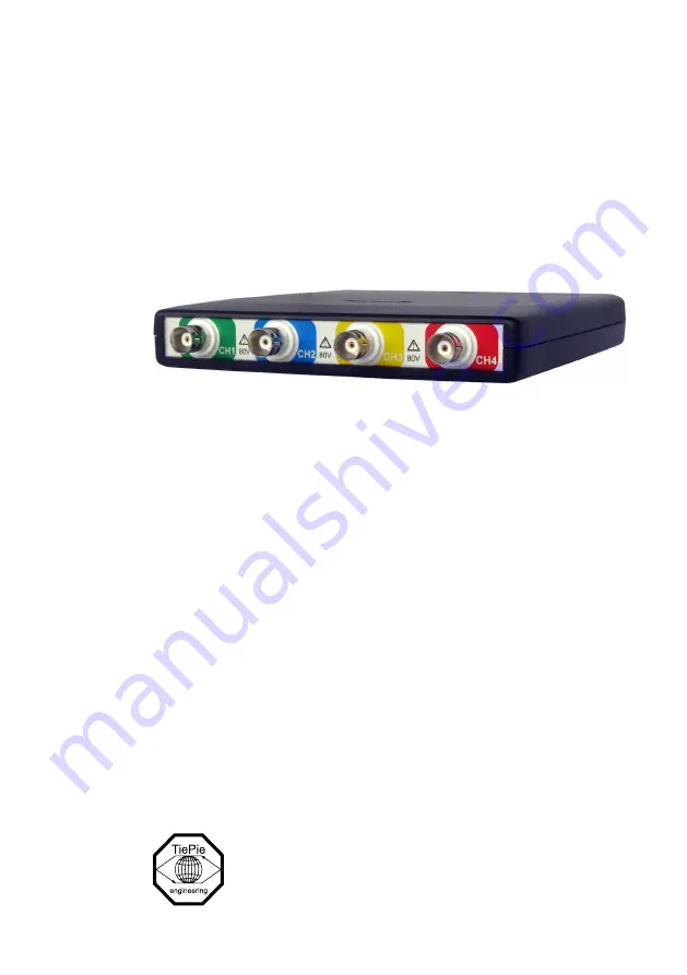
Page 31: ...tors are the main inputs of the acquisition system The isolated BNC connectors are not connected to the ground of the Handyscope HS6 DIFF 7 2 Power indicator A power indicator is situated at the top c...

Page 32: ...28 Chapter 7...

Page 33: ...cations of the dedicated power connector are Pin Dimension Description Center pin 1 3 mm positive Outside bushing 3 5 mm ground Figure 8 2 Power connector To power the instrument through the extensio...

Page 34: ...pe HS6 DIFF that can be used instead of a power adapter One end of this cable can be con nected to a second USB port on the computer the other end can be plugged in the dedicated power connector at th...

Page 35: ...nal that can be used to perform probe frequency compensations Pin 8 Power OUT has the same potential as the Handyscope HS6 DIFF power supply When the Handyscope HS6 DIFF is USB powered it is at USB po...

Page 36: ...ntilation slot is located with a fan behind it Figure 8 7 Ventilation slot Do not block the ventilation slot as this may cause the Handyscope HS6 DIFF becoming too hot Do not insert objects in the ven...

Page 37: ...200 V DC AC peak 10 kHz Maximum Common Mode voltage 200 mV to 800 mV ranges 2 V 2 V to 8 V ranges 20 V 20 V to 80 V ranges 200 V Common Mode Rejection Ratio 47 dB Bandwidth HS6D 1000 HS6D 500 HS6D 20...

Page 38: ...2 channels 50 MSa s3 25 MSa s3 10 MSa s 5 MSa s 2 5 MSa s Measuring 3 or 4 channels 25 MSa s4 12 5 MSa s4 5 MSa s 2 5 MSa s 1 25 MSa s 14 bit Measuring 1 channel 100 MSa s2 50 MSa s2 20 MSa s 10 MSa s...

Page 39: ...les 1 sample resolution Digital external trigger Input Extension connector pins 1 and 2 Range 0 to 2 5 V TTL Coupling DC Jitter 1 sample 9 4 Power Power From USB or external input Consumption 5 VDC 12...

Page 40: ...nectors 1 2 HDMI type C socket 9 9 Interface Interface USB 3 0 SuperSpeed 5 Gbit s USB 2 0 HighSpeed 480 Mbit s compatible 9 10 System requirements PC I O connection USB 2 0 USB 3 0 or USB 3 1 Operati...

Page 41: ...s various colors Suitable instrument Handyscope HS6 DIFF 9 13 Di erential attenuators Model TP DA10 Attenuation 10 x di erential Bandwidth 25 MHz Input impedance 10 M 15 pF Maximum input voltage 300 V...

Page 42: ...ator Clip TP AC80I green blue yellow red and 4 x black Alligator clips medium 8 x Alligator Clip TP AC10I green blue yellow red and 4 x black Alligator clips small 8 x Alligator Clip TP AC5 green blue...

Page 43: ...uggestions and or remarks regarding this manual please contact TiePie engineering Koperslagersstraat 37 8601 WL SNEEK The Netherlands Tel 31 515 415 416 Fax 31 515 418 819 E mail support tiepie nl Sit...

Page 44: ...TiePie engineering Handyscope HS6 DIFF instrument manual revision 2 27 February 2020...

Reviews: