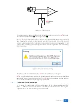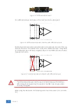
•
do not connect other cables to the attenuator than the ones that are sup-
plied with the instrument
•
do not touch the metal parts of the BNC’s when the attenuator is connected
to the circuit under test, they can carry a dangerous voltage. It will also in-
fluence the measurements and create measurement errors.
•
do not connect the outside of the two BNC’s of the attenuator to each other
as this will short circuit a part of the internal circuit and will create measure-
ment errors
•
do not connect the outside of the BNC’s of two or more attenuators that are
connected to different channels of the Handyscope HS6 DIFF to each other
•
do not apply excessive mechanical force to the attenuator in any direction
(e.g. pulling the cable, using the attenuator as handle to carry the Handy-
scope HS6 DIFF, etc.)
When the Handyscope HS6 DIFF is equipped with
Safe
Ground and the in-
puts are switched to single ended, using the diferential attenuator will lead
to significant measurement errors. Use attenuating oscilloscope probes
instead.
3.1.3
Differential test lead
The Handyscope HS6 DIFF comes with a special differential test lead. This test lead
is specially designed to ensure a good CMRR.
The special heat resistant differential test lead provided with the Handyscope HS6
DIFF is designed to be immune for noise from the surrounding environment.
The differential test lead is only immune for noise when used on a differen-
tial input. When the Handyscope HS6 DIFF is equipped with
Safe
Ground
and the inputs are switched to single ended, the diferential differential
test lead will
not
be immune for noise. Use standard shielded test leads
or oscilloscope probes instead.
3.2
Sampling
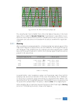
When sampling the input signal, samples are taken at fixed intervals. At these in-
tervals, the size of the input signal is converted to a number. The accuracy of this
number depends on the resolution of the instrument. The higher the resolution,
the smaller the voltage steps in which the input range of the instrument is divided.
The acquired numbers can be used for various purposes, e.g. to create a graph.
Introduction
11
Summary of Contents for Handyscope HS6 DIFF Series
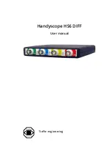
Page 1: ...Handyscope HS6 DIFF User manual TiePie engineering...
Page 6: ......
Page 21: ...Figure 3 15 over compensated Introduction 17...
Page 22: ...18 Chapter 3...
Page 25: ...Figure 4 3 Driver install Finished Driver installation 21...
Page 26: ...22 Chapter 4...
Page 32: ...28 Chapter 7...
Page 44: ...TiePie engineering Handyscope HS6 DIFF instrument manual revision 2 27 February 2020...

