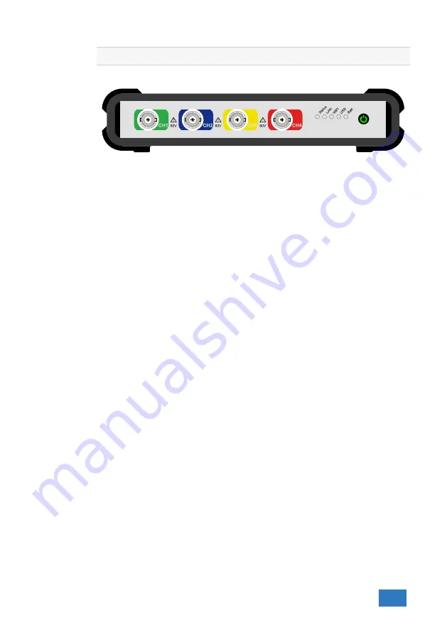
Front panel
9
Figure 9.1: Front panel
9.1
Channel input connectors
The CH1 – CH4 Isolated BNC connectors are the main inputs of the acquisition
system.
9.2
Power/Mode button
The
Power/Mode
button is situated at the right of the front of the instrument.
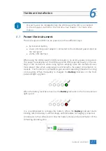
It is used to switch the mode of the WiFiScope WS6 DIFF between USB use and
LAN or WiFi use. To use the WiFiScope WS6 DIFF via LAN or WiFi, the network
interface must be enabled, by pressing the Power/Mode button. During initializing
the network interface, the Power/Mode button will blink green. When initialization
is finished, the indicator in the button will be lit continuously green.
When using the WiFiScope WS6 DIFF via USB, the network interface must be dis-
abled, by pressing the Power/Mode button again. The light in the button will go
off.
9.3
Status indicators
The WiFiScope WS6 DIFF has a number of status indicators, which can be lit to
indicate the status of the instrument.
9.3.1
Status
The status light indicates whether the WiFiScope WS6 DIFF is being used by soft-
ware or is not in use.
•
When lit continuously green, the WiFiScope WS6 DIFF is not being used, it is
available to be opened in software.
•
When lit continuously blue, the WiFiScope WS6 DIFF is in use, it is already
opened in software.
9.3.2
LAN
When the
LAN
indicator is lit, the WiFiScope WS6 DIFF is connected to a wired
network.
•
When lit continuously green, the WiFiScope WS6 DIFF has received a network
address via DHCP.
Front panel
39
Summary of Contents for WiFiScope WS6
Page 1: ...WiFiScope WS6 DIFF User manual USB Network WiFi Battery power TiePie engineering...
Page 6: ...IV...
Page 8: ...2 Chapter 1...
Page 10: ......
Page 14: ...8 Chapter 3...
Page 27: ...Figure 4 15 over compensated Introduction 21...
Page 28: ...22 Chapter 4...
Page 31: ...Figure 5 3 Driver install Finished Driver installation 25...
Page 32: ...26 Chapter 5...
Page 58: ...TiePie engineering WiFiScope WS6 DIFF instrument manual revision 2 27 February 2020...

