Theory of Operation
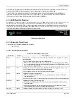
The outdoor end of the cable is attached to the LNB downconverter mounted on the antenna. The indoor end
connects to the DBR RF Input connector. The IFL cable uses F connectors on both ends.
The IFL cable is an important component of the receiver system. Proper cable selection and installation is
imperative to obtain optimal system performance. Appendix C: IFL Cable Characteristics provides detailed
information on the IFL cable, vendor sources, and connector installation.
2.1.4 DBR Satellite Receiver
The DBR is a multiple transmission rate digital data receiver. The DBR receiver chassis, shown in Figure 2-3, is a
standard 19” rack-mount design with built-in handles. The DBR chassis is designed to meet worldwide
electromagnetic compatibility (EMC), safety, and power requirements. Its lightweight aluminum construction is
optimized to provide strength and EMC. The DBR contains a universal autosensing power supply, allowing the
unit to accommodate virtually any standard AC power source.
Figure 2.3 DBR Unit
2.1.5 Using the Front Panel
The front panel of the DBR displays the following:
•
LED indicators
2.1.5.1 Front Panel Indicators
Table 2.2 Front Panel Indicators
Indicator
Color
Description
Power Green
Indicates the unit is powered on and changes color based on the presence of any
operating fault.
•
If the Power LED is green, the unit is powered on.
•
If the Power LED is off, then the power supply is not functioning properly. Refer
to the Troubleshooting section to determine whether the AC power source or the
internal power supply is faulty.
Status
Red
Indicates the state of the status relay. By default, all faults trigger the status relay.
•
If the Status LED is Red, the status relay is active
•
If the Status LED is off, then the status relay is inactive.
Event Amber
Indicates
the
state of the event log.
•
If the Event LED is Amber, one or more events have occurred since the last
acknowledgement.
•
If the Event LED is off, no events have occurred since the last acknowledgement.
Ethernet Green
Indicates
the
state of the Ethernet port.
•
If the Ethernet LED is green, the Ethernet port is connected to another active
Ethernet device.
•
If the Ethernet LED is off, then the Ethernet port is not connected to another
active Ethernet device or the port has been shut down.
Rx Sync
Green
Indicates whether the demodulator has synchronized (or “locked”) to the
Tiernan DBR3000
Page
2-11
Summary of Contents for DBR3000
Page 2: ...Overview Page 1 2 Tiernan DBR3000 ...
Page 6: ...Warranty Policy Page vi Tiernan DBR3000 ...
Page 10: ...Preface Page x Tiernan DBR3000 ...
Page 14: ...Safety Precautions Page xiv Tiernan DBR3000 ...
Page 64: ......
Page 73: ...Troubleshooting Figure C 1 Coax Cable and F Connector Assembly Tiernan DBR3000 Page B 5 ...

