Maintenance and Troubleshooting
To ensure compliance with EMC standards, all signal cables connected to the receiver should
be shielded. The shield must be properly terminated to the mating connector.
4.7.1 Data
Connector Type: DB-25, Female (Bottom Row)
The Data port provides a synchronous RS-422 clock and data output. This interface operates synchronously with
the output data being valid on the falling edge of the receive timing clock that is also provided.
4.7.2 AUX (Auxiliary)
Connector Type: DB-15, Female (Bottom Row)
The auxiliary port provides a connection to a variety of signals for optional use, including:
•
Status relay contacts
•
Synchronous RS-422 receive clock/data output
4.7.2.1 Status Relay
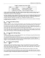
The Status Relay contacts are made at this connector. The Status Relay output provides the capability for an
external indication of errors in the satellite receiver system operation. The Status Relay tracks the front panel
Fault indicator and consists of contact closures (both normally open and normally closed presentations) that
remains inactive during normal operation (Figure 4-2).
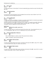
A powerful feature of the Status Relay is its ability to be programmed to trigger when specific user-selected fault
conditions are detected while ignoring others. This allows the status relay actions to be customized for the
conditions at a specific receiver installation. The status relay mask (SR) command provides this customizing
ability. (For specific details, refer to the chapter on Remote Monitor and Control Operation.)
Both normally open and normally closed presentations of the status relay are available on the Status Relay
connector. The normally open relay pins will present an open circuit when the unit power is off or when an
unmasked fault is present. Conversely, the normally closed relay output will present a short circuit when power is
off or an unmasked fault is present. The logic of the relay, i.e., open or closed, may be reversed using the SS
command as described in the chapter on commands and codes.
The Status Relay output should not be used to switch currents greater than 1 amp, voltages
higher than 100 volts, or total power higher than 25 VA.
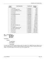
4.7.2.2 RS-422 Data Output
The data stream is on this connector as RS-422 data and clock signal pairs. This interface operates
synchronously with the output data being valid on the falling edge of the receive timing clock that is also provided.
4-6
Tiernan DBR3000
Summary of Contents for DBR3000
Page 2: ...Overview Page 1 2 Tiernan DBR3000 ...
Page 6: ...Warranty Policy Page vi Tiernan DBR3000 ...
Page 10: ...Preface Page x Tiernan DBR3000 ...
Page 14: ...Safety Precautions Page xiv Tiernan DBR3000 ...
Page 64: ......
Page 73: ...Troubleshooting Figure C 1 Coax Cable and F Connector Assembly Tiernan DBR3000 Page B 5 ...

